| Register |
BaseBoard Mode Register Value |
Alternate Mode Register Value |
| Control |
0 |
3 |
| DataPort C |
1 |
2 |
| DataPort B |
2 |
1 |
| DataPort A |
3 |
0 |
| R/W |
Addr + |
BaseBoard Mode |
Alternate Mode |
| W |
0 |
Section 1 - Control Register |
Section1 - Port A Data |
| R/W |
1 |
Section 1 - Port C Data |
Section1 - Port B Data |
| R/W |
2 |
Section 1 - Port B Data |
Section 1 - Port C Data |
| R/W |
3 |
Section 1 - Port A Data |
Section 1 - Control Register |
| W |
4 |
Section 2 - Control Register |
Section 2 - Port A Data |
| R/W |
5 |
Section 2 - Port C Data |
Section 2 - Port B Data |
| R/W |
6 |
Section 2 - Port B Data |
Section 2 - Port C Data |
| R/W |
7 |
Section 2 - Port A Data |
Section 2 - Control Register |
| W |
8 |
Section 3 - Control Register |
Section 3 - Port A Data |
| R/W |
9 |
Section 3 - Port C Data |
Section 3 - Port B Data |
| R/W |
10 (A) |
Section 3 - Port B Data |
Section 3 - Port C Data |
| R/W |
11 (B) |
Section 3 - Port A Data |
Section 3 - Control Register |
| W |
12 (C) |
Section 4 - Control Register |
Section 4 - Port A Data |
| R/W |
13 (D) |
Section 4 - Port C Data |
Section 4 - Port B Data |
| R/W |
14 (E) |
Section 4 - Port B Data |
Section 4 - Port C Data |
| R/W |
15 (F) |
Section 4 - Port A Data |
Section 4 - Control Register |
| DeskTop Unit |
Connector |
8255 Data Port |
LabPac32 Port |
| 1 |
1 |
A |
0 |
| 1 |
1 |
B |
1 |
| 1 |
1 |
C |
2 |
| 1 |
2 |
A |
3 |
| 1 |
2 |
B |
4 |
| 1 |
2 |
C |
5 |
| 1 |
3 |
A |
6 |
| 1 |
3 |
B |
7 |
| 1 |
3 |
C |
8 |
| 1 |
4 |
A |
9 |
| 1 |
4 |
B |
10 |
| 1 |
4 |
C |
11 |
| 2 |
1 |
A |
12 |
| 2 |
1 |
B |
13 |
| 2 |
1 |
C |
14 |
| 2 |
2 |
A |
15 |
| 2 |
2 |
B |
16 |
| 2 |
2 |
C |
17 |
| 2 |
3 |
A |
18 |
| 2 |
3 |
B |
19 |
| 2 |
3 |
C |
20 |
| 2 |
4 |
A |
21 |
| 2 |
4 |
B |
22 |
| 2 |
4 |
C |
23 |
| 3 |
1 |
A |
24 |
| 3 |
1 |
B |
25 |
| 3 |
1 |
C |
26 |
| 3 |
2 |
A |
27 |
| 3 |
2 |
B |
28 |
| 3 |
2 |
C |
29 |
| 3 |
3 |
A |
30 |
| 3 |
3 |
B |
31 |
| 3 |
3 |
C |
32 |
| 3 |
4 |
A |
33 |
| 3 |
4 |
B |
34 |
| 3 |
4 |
C |
35 |
| 4 |
1 |
A |
36 |
| 4 |
1 |
B |
37 |
| 4 |
1 |
C |
38 |
| 4 |
2 |
A |
39 |
| 4 |
2 |
B |
40 |
| 4 |
2 |
C |
41 |
| 4 |
3 |
A |
42 |
| 4 |
3 |
B |
43 |
| 4 |
3 |
C |
44 |
| 4 |
4 |
A |
45 |
| 4 |
4 |
B |
46 |
| 4 |
4 |
C |
47 |

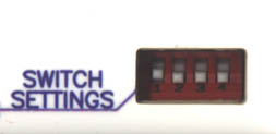
| SW1 |
SW2 |
SW3 |
SW4 |
FUNCTION |
|
| DN |
DN |
x |
x |
 |
UNIT #1 SELECTED (DEFAULT) |
| DN |
UP |
x |
x |
 |
UNIT #2 SELECTED |
| UP |
DN |
x |
x |
 |
UNIT #3 SELECTED |
| UP |
UP |
x |
x |
 |
UNIT #4 SELECTED |
| x |
x |
DN |
x |
 |
BASEBOARD MODE (DEFAULT) |
| x |
x |
UP |
x |
 |
ALTERNATE MODE |
| x |
x |
x |
DN |
 |
DISABLE INTERRUPT (DEFAULT) |
| x |
x |
x |
UP |
 |
ENABLE INTERRUPT |

 |
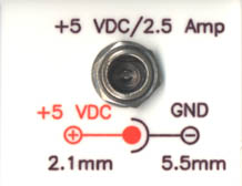 |
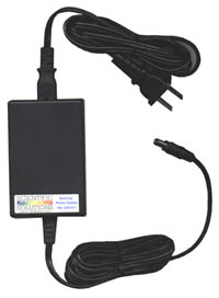
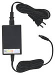
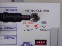
| DeskTop Power Supply (Power supply may vary from the picture shown) |
DeskTop Power Connector |
 |
||
 |
 |
 |
 |
 |
 |

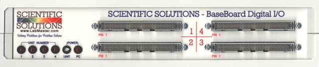
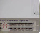
| Digital
I/O
Section #1 P137 (40pin header) P150 (50pin header) P1 (40pin header) |
Digital
I/O
Section #4 P437 (40pin header) P450 (50pin header) P4 (40pin header) |
| Digital
I/O
Section #2 P237 (40pin header) P250 (50pin header) P2 (40pin header) |
Digital
I/O
Section #3 P337 (40pin header) P350 (50pin header) P3 (40pin header) |
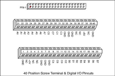
| A0 |
A1 |
A2 |
A3 |
A4 |
A5 |
A6 |
A7 |
C5 |
C7 |
C1 |
C3 |
G |
G |
G |
NC |
NC |
+5 |
NC |
G |
| 21 |
22 |
23 |
24 |
25 |
26 |
27 |
28 |
29 |
30 |
31 |
32 |
33 |
34 |
35 |
36 |
37 |
38 |
39 |
40 |
| 1 |
2 |
3 |
4 |
5 |
6 |
7 |
8 |
9 |
10 |
11 |
12 |
13 |
14 |
15 |
16 |
17 |
18 |
19 |
20 |
| G |
NC |
+5 |
NC |
NC |
G |
G |
G |
C4 |
C6 |
C0 |
C2 |
B0 |
B1 |
B2 |
B3 |
B4 |
B5 |
B6 |
B7 |
| G |
G |
G |
G |
G |
G |
G |
G |
G |
G |
G |
G |
G |
G |
G |
G |
G |
G |
G |
G |
G |
G |
G |
G |
G |
| 2 |
4 |
6 |
8 |
10 |
12 |
14 |
16 |
18 |
20 |
22 |
24 |
26 |
28 |
30 |
32 |
34 |
36 |
38 |
40 |
42 |
44 |
46 |
48 |
50 |
| 1 |
3 |
5 |
7 |
9 |
11 |
13 |
15 |
17 |
19 |
21 |
23 |
25 |
27 |
29 |
31 |
33 |
35 |
37 |
39 |
41 |
43 |
45 |
47 |
49 |
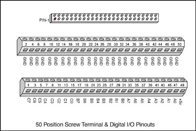
| C7 |
C6 |
C5 |
C4 |
C3 |
C2 |
C1 |
C0 |
B7 |
B6 |
B5 |
B4 |
B3 |
B2 |
B1 |
B0 |
A7 |
A6 |
A5 |
A4 |
A3 |
A2 |
A1 |
A0 |
+5 |
| G |
C7 |
C6 |
C5 |
C4 |
C3 |
C2 |
C1 |
C0 |
A7 |
A6 |
A5 |
A4 | A3 | A2 | A1 |
A0 |
NC |
NC |
NC |
| 21 |
22 |
23 |
24 |
25 |
26 |
27 |
28 |
29 |
30 |
31 |
32 |
33 |
34 |
35 |
36 |
37 |
38 |
39 |
40 |
| 1 |
2 |
3 |
4 |
5 |
6 |
7 |
8 |
9 |
10 |
11 |
12 |
13 |
14 |
15 |
16 |
17 |
18 |
19 |
20 |
| NC |
NC |
B7 |
B6 |
B5 |
B4 |
B3 |
B2 |
B1 |
B0 |
G |
NC |
G |
NC |
G |
NC |
G |
+5 |
G |
+5 |
|
|
|
 |
 |


 |
 |
 |
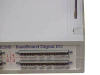
| (1). Remove the cover of the DeskTop Unit as
previous
detailed in this document |
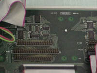
(2). The back panel can be lifted out and moved
to
the side to gain easier access to the DeskTop internal connections |
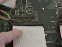
(3). Remove the existing 40pin connector from
the
P1, P2, P3 or P4 header (Depending on the section obtaining the module) |
 |
|
|
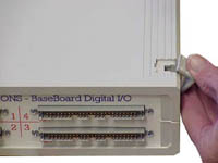
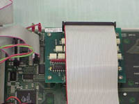
| (4). With the 40pin cable removed, you have
access
to the header connectors. The Opto modules have a 40pin socket
connector
that will connect to the 40pin header connectors P1, P2, P3 or P4. |
(5). Remove the 40pin cable from the front
panel.
Note that the 40pin connectors have an adapter attached to them.
Leave
the adapter on the connector, and remove the screws that hold the
adapter
to the front panel. |
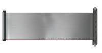
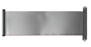
(6). You will need a 50pin ribbon cable to
replace
the 40pin you just removed. The 50pin ribbon cable is not
supplied
with the DeskTop Unit and should be obtained from Scientific Solutions
when
you purchase your Opto Module. |
 |
 |
|
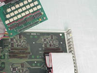
| (7). Install the 50pin ribbon cable to the front panel. Be sure the red stripe (pin 1) of the cable is oriented correctly (towards the left had side of the front panel). | (8). Orient the Opto Module to install the 40pin socket connector of the Opto onto the 40pin header connector (P1, P2, P3 or P4) of the DeskTop unit. | (9). With the pins lined up properly, press down on the Opto module to make a good connection of the 40pin connectors. |
 |
 |
|
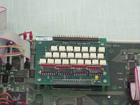
| (10). Connect the 50pin socket connector of the ribbon cable to the 50pin header connector on the Opto module. | (11). Replace the back panel |
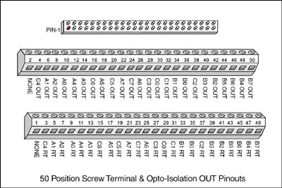
In the above diagram, the section within the dotted lines shows the circuit on the Opto-Isolation Out Module. A single BaseBoard Digital output is converted to an optically isolated signal pair: RT and OUT. The signal pairs for each Digital Output are located on the module’s 50 pin header.


| NC |
C4 OUT |
A1 OUT |
A2 OUT |
A0 OUT |
A4 OUT |
A3 OUT |
C6 OUT |
A5 OUT |
C5 OUT |
A7 OUT |
C7 OUT |
A6 OUT |
C3 OUT |
C0 OUT |
C1 OUT |
B1 OUT |
B0 OUT |
C2 OUT |
B3 OUT |
B2 OUT |
B5 OUT |
B6 OUT |
B4 OUT |
B7 OUT |
| 2 |
4 |
6 |
8 |
10 |
12 |
14 |
16 |
18 |
20 |
22 |
24 |
26 |
28 |
30 |
32 |
34 |
36 |
38 |
40 |
42 |
44 |
46 |
48 |
50 |
| 1 |
3 |
5 |
7 |
9 |
11 |
13 |
15 |
17 |
19 |
21 |
23 |
25 |
27 |
29 |
31 |
33 |
35 |
37 |
39 |
41 |
43 |
45 |
47 |
49 |
| NC |
C4 RT |
A1 RT |
A2 RT |
A0 RT |
A4 RT |
A3 RT |
C6 RT |
A5 RT |
C5 RT |
A7 RT |
C7 RT |
A6 RT |
C3 RT |
C0 RT |
C1 RT |
B1 RT |
B0 RT |
C2 RT |
B3 RT |
B2 RT |
B5 RT |
B6 RT |
B4 RT |
B7 RT |
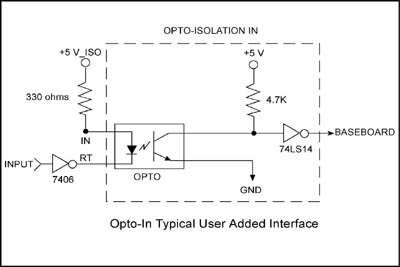
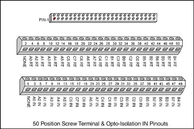
In the above diagram, the section within the dotted lines shows the circuit on the Opto-Isolation In Module. A signal pair, RT and IN, is converted to a single Base Board Digital input. The signal pairs for each Digital Input are located on the module’s 50 pin header.
| NC |
A0 RT |
A2 RT |
A1 RT |
A3 RT |
A4 RT |
A5 RT |
C5 RT |
C7 RT |
C6 RT |
A6 RT |
A7 RT |
C4 RT |
C1 RT |
B1 RT |
C3 RT |
B0 RT |
C2 RT |
C0 RT |
B5 RT |
B2 RT |
B6 RT |
B3 RT |
B7 RT |
B4 RT |
| 2 |
4 |
6 |
8 |
10 |
12 |
14 |
16 |
18 |
20 |
22 |
24 |
26 |
28 |
30 |
32 |
34 |
36 |
38 |
40 |
42 |
44 |
46 |
48 |
50 |
| 1 |
3 |
5 |
7 |
9 |
11 |
13 |
15 |
17 |
19 |
21 |
23 |
25 |
27 |
29 |
31 |
33 |
35 |
37 |
39 |
41 |
43 |
45 |
47 |
49 |
| NC |
A0 IN |
A2 IN |
A1 IN |
A3 IN |
A4 IN |
A5 IN |
C5 IN |
C7 IN |
C6 IN |
A6 IN |
A7 IN |
C4 IN |
C1 IN |
B1 IN |
C3 IN |
B0 IN |
C2 IN |
C0 IN |
B5 IN |
B2 IN |
B6 IN |
B3 IN |
B7 IN |
B4 IN |
| Number of bits |
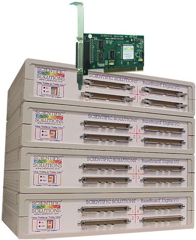
96 bits of Digital I/O per DeskTop Unit (maximum of 384 bits per PCI card) |
| Programmable Modes |
|
| Data Transfer |
Programmed I/O |
| Logic Thresholds |
TTL |
| Current Source | 15ma |
| Current Sink | 64 ma |
| Isolator Type | 4N25 |
| Input Voltage | 30 Volts |
| Input Current | 80 Milliamps |
| Input Reverse Voltage | 3 Volts maximum |
| Input Isolation | 2500 Volts maximum |
| Switching Times | |
| Rise | 3 microseconds maximum |
| Fall | 3 microseconds maximum |
| Isolator Type | TIL128 |
| Collector Base Voltage | 70 Volts maximum |
| Collector Emitter Voltage | 30 Volts maximum |
| Emitter Collector Voltage | 7 Volts maximum |
| Output Current | 80 milliamps maximum |
| Isolation | 2500 Volts maximum |
| Switching Times | |
| Rise | 300 microseconds maximum |
| Fall | 5 microseconds maximum |
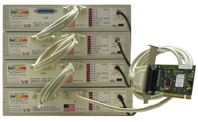
| Bus Interface | Single 32-bit or 64-bit PCI slot |
| IRQ Channels | PCI BIOS Plug-and-Play auto-select |
| Address | PCI BIOS Plug-and-Play auto-select |
| Bus Load | 1 TTL load/bus line maximum |
| DeskTop Power Supply |
5v DC regulated, 3A |
| Operating Temperature | 0º to 70º Celsius |
| Storage Temperature | -25º to +85º Celsius |
| Relative Humidity | To 95% non-condensing |
| Agency Approvals | FCC Class A, CE-Mark |