

This document describes Scientific Solutions' Elmo test system.
Description
Components
System Hardware Connections
LabRack Computer
System - Keyboard, Monitor, Mouse and Power
LabRack Computer System
to MCU
MCU to DCU
Device Connections
U/D Connection
DCU connections
for Electric Window Motors
Standard Motor Connection
Smart Motor Connection
T Connection & Temperature Probes
Voltage Input Connection
System Power Up
Status Lights
Software Introduction
Annual Calibration & Licensing
Requirements
Part Numbers
Specifications
Software License
Document Notice
Limited Warranty
Trademark Notification
The Scientific Solutions Elmo test system is designed for the durability testing of electric motors and systems. The Elmo system incorporates a modular design for ease of expansion. The system contains software and programmable hardware to control electric window motor UP/DOWN position, detect stall over-current conditions and monitor failures. It consists of a self-contained computer incorporating a Scientific Solutions data acquisition system that connects to a Master Control Unit (MCU). The MCU has one connector for cabling back to the computer and four additional connectors for cabling to Device Control Units (DCU). Each DCU can control up to four devices. A fully configured system, can simultaneously test 16 electric window motors, i.e. four "virtual" cars.
The Scientific Solutions Electric Motor Tester consists of a LabRack Computer System, a LabRack Master Control Unit and from one to four Device Control Units and the Elmo software. The following table describes these various components:
LabRack Computer System:
|
|
Master Control Unit: (MCU)The Master Control Unit (MCU) decodes the signals from the
computer system and creates individual interfaces for connecting up to
four Device Control Units (DCU). The MCU has logic to determine
the quantity of DCUs attached and reports this back to the computer
system so the control software can automatically determine the test
matrix. |
|
Cable Connection: LabRack Computer System and Master Control Unit:The LabRack Computer System and the Master Control Unit are generally supplied as a set, since each test system requires one of each. Also supplied with this set is a cable that is used to connect the two units. |
|
Device Control Unit: (DCU)The Device Control Unit (DCU) contains the necessary high current outputs and associated control logic to directly control four devices. The back of the DCU has a single connection to connect to one of the four connections on the back of the MCU. The front of the DCU has four sets of connections labeled
Device #1, Device #2, Device #3 and Device #4. It also has an
additional
set of connections labeled Voltage Input. |
|
Cable Connection: Master Control Unit to Device Control Unit:Each test set up can consist of from one to four Device Control Units. Each DCU is supplied with a cable that is used to connect the DCU to the MCU. |
|
Elmo Software:
|
|
The following procedure should be used to connect the various system components.
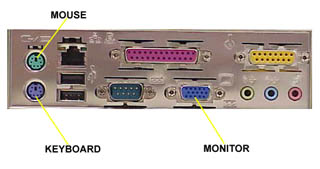
Connect a monitor, keyboard and mouse to
the
LabRack Computer System. You can also connect the power cable to the
Computer
System and the monitor. Be sure that the Computer System and monitor
are
powered-off before connecting the additional components.
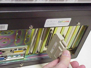
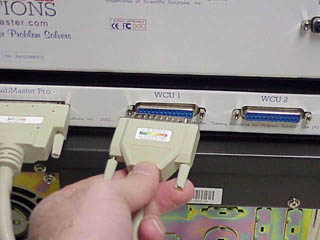
Connect the Computer System to the MCU
with
the supplied cable. Note that this cable contains a high-density pin
connector
on each end. These connectors are designed for only one correct
alignment. Make sure the cable connections and the connections on the
back of the Computer
System and the MCU are properly aligned before trying to make the
connection. Be careful not to bend any of the pins. After the
connections are properly
made, use the thumb screws to secure the connectors on the back of the
Computer
System and the MCU.
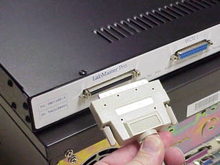
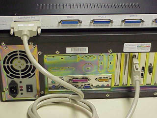
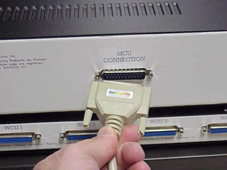
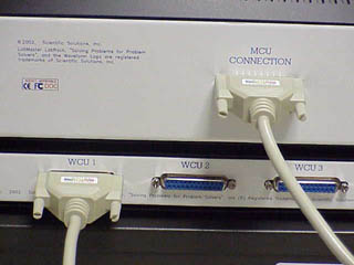
Connect the MCU to the DCUs. Each DCU is
supplied
with a cable for this connection. The MCU can accommodate from one to
four
DCUs. Connect the first DCU to the "Device Control Unit 1" connection.
If
you are using a second, third or fourth DCU unit, then connect these to
the
corresponding Device Unit connection. Do not skip DCU connections -
start
with number 1 for the first, 2 for the second, 3 for the third and so
on. These connectors are designed for only one correct alignment. Make
sure
the cable connections and the connections on the back of the MCU and
DCU
are properly aligned before trying to make this connection. Be careful
not
to bend any of the pins. After the connections are properly made, use
the
thumb screws to secure the connectors on the back of the MCU and DCU.
The Device
Control
Unit has four sections;

Each section has a U, D and T connector.
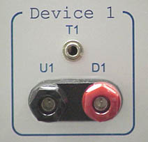
U/D Connection:
Direction: Output from the DCU
Description: The voltage that is applied to the Voltage
Input terminals on the front of the DCU are available on the U/D
output
connections under control of the software. The software controls the
on/off
condition of the U/D voltage and also the polarity of the U/D outputs.
DCU Connections for Electric Window Motors
The design of the Elmo system makes it idea for testing Electric Window
Motors. A single DCU can control either
Standard Motors or Smart Motors. You can run a test with a mix of both
Standard
and Smart Motors - you just have to connect each motor type to a
different
DCU. For example, if a test requires 1 Standard Motor and 1 Smart
Motor,
then you would need 2 DCUs' - one for connection to the Standard Motor
and
one for connection of the Smart Motor. Since each Elmo system can have
up
to 4 DCUs, there is quite a bit of versatility in the testing of
electric
window motors.
The following charts indicate the correct connections to make for each
type
of motor. The last two columns of the charts indicate the voltage that
will
be present on the U/D terminals corresponding to the window direction
(UP
or DN).
Standard Motor Connection
|
Standard |
Motor |
Device # |
DCU |
Voltage |
Voltage |
|
1 |
UP control |
Device # 1 |
U |
+V |
GND |
|
1 |
DOWN control |
Device # 1 |
D |
GND |
+V |
|
2 |
UP control |
Device # 2 |
U |
+V |
GND |
|
2 |
DOWN control |
Device # 2 |
D |
GND |
+V |
|
3 |
UP control |
Device # 3 |
U |
+V |
GND |
|
3 |
DOWN control |
Device # 4 |
D |
GND |
+V |
|
4 |
UP control |
Device # 4 |
U |
+V |
GND |
|
4 |
DOWN control |
Device # 4 |
D |
GND |
+V |
Since each Standard Motor requires one
Device
section, a DCU can control up to 4 Standard Motors.
A system with four DCUs can therefore test up to 16 Standard Motors.
Note: If the wiring is reversed, then the window direction will be
opposite
to what is expected.
Smart Motor Connection
|
Smart |
Motor |
Device # |
DCU |
Voltage |
Voltage |
|
1 |
UP control |
Device # 1 |
U |
+V |
float |
|
1 |
DOWN control |
Device # 1 |
D |
float |
+V |
|
1 |
+V power |
Device # 2 |
D |
+V |
+V |
|
1 |
Ground |
Device # 2 |
U |
GND |
GND |
|
2 |
UP control |
Device # 3 |
U |
+V |
float |
|
2 |
DOWN control |
Device # 4 |
D |
float |
+V |
|
2 |
+V power |
Device # 4 |
D |
+V |
+V |
|
2 |
Ground |
Device # 4 |
U |
GND |
GND |
Since each Smart Motor requires two Device sections, a DCU can
control
up to 2 Smart Motors.
A system with four DCUs can therefore test
up to
8 Smart Motors.
Note: If the wiring is reversed, then the motors will not operate
properly.
T Connection:
Direction: Input to the DCU
Description: This input terminal is used for connection to a Scientific
Solutions
Temperature probe. A temperature probe allows the system to make
temperature
measurements. The T connector is a 3.5mm Stereo Jack. The temperature
probe
can typically make measurements from -40º Celsius to +125º Celsius
(refer
to the specification section of this document).
The temperature probe is a cylindrical device
approximately
1" long and 1/3" in diameter.
It has a single 3.5mm Stereo Plug connection.

You can insert the temperature probe directly into the front of the DCU
unit
to verify its operation. To remotely locate the temperature probe, you
need
to use a cable. The cable needs a 3.5mm Stereo Plug on one end and a
3.5mm
Stereo Jack on the other end.
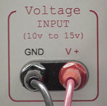
Connect the Voltage Input on the front of the DCU to an external
voltage
source. Be sure the VOLT and GROUND connections are made to the correct
terminals. If you have multiple DCUs and are using one power supply to
power them all,
then each DCU should have a VOLT and GROUND connection back to the
supply,
i.e. avoid connecting to one of the DCU's and daisy-chain connecting
the
power to the additional DCUs and this could result in an unreliable
test setup.
Note: The external power supply must have sufficient capabilities to
provide
enough electrical current to sustain the stalling of the window motors.
Each
window motor can require up to 25 amps of stall current. If four
windows
are tested one-at-a-time (i.e. they are not all stalling in the UP or
DN
condition at the same time, but are staggered during the test) then an
external
25 amp supply is sufficient. However, if four windows are
simultaneously
tested (that is the all stall at the same time), then the external
voltage
should be able to supply 100 amps of current (25 amps per stall x 4
stalls). A fully configured system with four DCUs requires (25 amps /
motor) * (4
motors / dcu) * (4 dcu / mcu) = 400 amps of +Voltage.
Make sure your test configuration (as set up in the software) matches the capabilities of your external power supply.
DO NOT EXCEED the Voltage Input range of the DCU of +10 volt to +15 volt
Make sure the external supply VOLT and GROUND are made to the correct terminals on the front of the DCU.
After the proper connections have been made, you should power up the computer system and the external supply voltage. The system has some inherent safety features, one of these being that the external supply voltage is not present on the motor connections until the software has initialized the system. However, caution should always be exercised and it is good practice to verify all the connections and the correct polarity of the external voltage connections before applying any power.
In addition to the information provided on the computer screen by
the software,
lights on the various components can be used to determine the status of
the
equipment.
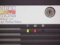
Computer System:
Green Light - indicates computer is ON
Red Light - indicates access to the
internal
hard disk drive
Master Control Unit:
The Master Control Unit has five LED light indications. One for System
Power
(Red LED) and Four for Device Control Units (Blue LED):
System Power - Indicates connection to the
computer
and that computer power is ON

Device Control Unit - Indicates
connections
made to DCUs. There are four lights, one for each DCU that can be
connected.

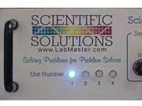
Device Control Unit - Unit Number:
The Device Control Unit has
four
Blue LED light indicators.
Unit Number - Indicates connection to the MCU and that the
software
has initialized the DCU. Only one of the Unit Number lights is
illuminated. The Unit Number light will only illuminate when the
connections are made
(DCU->MCU & MCU->Computer), power is ON, AND the
software
is running (which turns ON the appropriate Unit Number light). As the
DCU
is initialized all the lights may blink, but once the initialization is
finished,
only one of the four lights will be illuminated to indicate the
particular
Unit Number. The software can also use the Unit Number light to
indicate
the status of a test - refer to the software documentation for details.
Software
When the test system is powered on, the computer will complete a
boot-up
sequence. Once this is complete, you can start the test software by
selecting
its icon on the computer desktop.
Once you start the software, you will need to create the test you would
like
to run. The software allows you to define tests with information such
as
the number of DCUs to use, the type of motor connected to each DCU,
duration
of test in cycles or time, and various measurements to make and actions
to
take when the measurements exceed your limits. The software allows you
to save and re-load the test configuration.
Refer to the Software's on-line help for details
The Elmo system as delivered is fully tested and calibrated. Annual calibration should be maintained for proper system operation. A label on the front of each system component indicates its serial number, calibration date, and calibration due date. The software license is also renewable on an annual basis. Scientific Solutions provides calibration of the equipment and renewal of the software license. Please contact Scientific Solutions at support@Scientific-Solutions.com to arrange for your annual calibration and software license renewal.
|
Part Number |
Description |
Contents |
|
815306 |
LabRack Computer System and Master Control Unit. |
The LabRack Computer System and the Master Control Unit are generally supplied as a set, since each test system requires one of each |
|
|
LabRack Computer System |
|
|
|
Master Control Unit |
|
|
815307 |
Device Control Unit |
|
|
815308 |
Temperature Probe |
|
|
DCU: |
|
||
|
DCU: |
Software controlled polarity |
||
|
DCU: |
|
||
|
DCU: |
|
||
|
Temperature Probe |
-40º Celsius to +125º Celsius (+/- 2º C) |
||
|
Computer System |
Universal Switching Power Supply |
||
|
Environmental: |
Operating Temperature |
0º to 70º Celsius |
|
|
Storage Temperature |
-25º to +85º Celsius |
||
|
Relative Humidity |
To 95% non-condensing |
||
|
Agency Approvals |
FCC Class A, CE-Mark |
||
IMPORTANT:
THIS IS A LEGAL AGREEMENT BETWEEN YOU (EITHER AN INDIVIDUAL OR AN
ENTITY)
AND SCIENTIFIC SOLUTIONS, INC. ("SSI"). USING THIS SOFTWARE CONSTITUTES
ACCEPTANCE
OF THE TERMS AND CONDITIONS SET FORTH IN THIS AGREEMENT. IF YOU AGREE
TO
THE TERMS AND CONDITIONS OF THIS AGREEMENT, THEN YOU MAY USE THE
SOFTWARE.
IF YOU DO NOT AGREE TO THE TERMS AND CONDITIONS OF THIS AGREEMENT OR
HAVE
QUESTIONS REGARDING THIS AGREEMENT, THEN DO NOT USE THE SOFTWARE.
TERMS:
The conditions of the terms covers the software, including any
accompanying
documentation ("the Software"). This Software is intended to be used
with
Scientific Solutions hardware. Scientific Solutions owns all right,
title
and interest to the Software. You have not purchased this product, but
by
acceptance of the terms you are granted a nonexclusive, nontransferable
license
to use the product according to the terms set forth in this agreement.
This
license is granted only to the original party acquiring the product.
The
Software is owned by Scientific Solutions and is protected by United
States
patent and copyright laws and international treaty provisions. Title to
the
Software, all copies thereof (in whole or in part, and in any form),
and
all rights therein, including but not limited to all rights in patents,
copyrights,
trademarks, and trade secrets applicable thereto, shall remain vested
in
Scientific Solutions. The Software contains valuable proprietary rights
of Scientific Solutions. There is no transfer to You of any title of
ownership
of the Product or any portion thereof or any proprietary rights related
to
the Product. You agree to hold the Product in confidence and to take
all
reasonable steps to prevent unauthorized disclosure or use of the
Product.
You will place the same copyright and proprietary rights notices on any
copy
of the software as appears on the original. All rights in and to the
Software
not expressly granted to you in this Agreement are reserved to
Scientific
Solutions.
SOFTWARE USE:
You may use the Software for your internal use only on one computer
with Scientific
Solutions hardware. You shall have no other rights in the Software,
whether
express, implied, arising by estoppel or otherwise.
Scientific Solutions explicitly prohibits you from and denies you
permission
to:
(1) distribute, rent, lease, sell, sublicense, assign, or otherwise
transfer
the Software, in whole or in part, to third parties for commercial or
for
non-commercial use; or
(2) modify, disassemble, reverse engineer, or decompile the Software,
or otherwise
reduce any part of the Software to any human readable form.
SUPPORT:
Scientific Solutions is under no obligation to provide you with any
support,
updates, or maintenance of the Software. The Software is subject to
change
or withdrawal at any time without notice.
LICENSE FEE:
The software may incur a yearly license renewal fee. Payment of this
fee
is mandatory for continual use of the software.
WARRANTY DISCLAIMER:
The Software is provided to you on an "AS IS" basis, without warranty
of
any kind.
TO THE MAXIMUM EXTENT PERMITTED BY APPLICABLE LAW, SCIENTIFIC SOLUTIONS
HEREBY
EXPRESSLY DISCLAIMS ALL WARRANTIES OR CONDITIONS, EITHER EXPRESS OR
IMPLIED,
INCLUDING, BUT NOT LIMITED TO ANY IMPLIED WARRANTIES OF MERCHANTABILITY
OR
FITNESS FOR A PARTICULAR PURPOSE, AND ANY WARRANTIES THAT MAY ARISE
FROM
USAGE OF TRADE OR COURSE OF DEALING. SCIENTIFIC SOLUTIONS MAKES NO
WARRANTIES
AND EXPRESSLY DISCLAIM ANY IMPLIED WARRANTIES OF TITLE OR
NON-INFRINGEMENT.
EXCLUSIONS:
Scientific Solutions does not warrant, guarantee, or make any
representations
as to the correctness, accuracy, or reliability of the Software.
Scientific
Solutions does not warrant that operation of the Software will be
uninterrupted
or error-free.
YOU ARE SOLELY RESPONSIBLE FOR DETERMINING THE APPROPRIATENESS OF USING
THE
SOFTWARE AND ASSUME ALL RISKS ASSOCIATED WITH THE USE OF THE SOFTWARE.
TO
THE MAXIMUM EXTENT PERMITTED BY APPLICABLE LAW, IN NO EVENT SHALL
SCIENTIFIC
SOLUTIONS OR ITS DIRECTORS, OFFICERS, EMPLOYEES, AND AGENTS BE LIABLE
FOR
ANY DAMAGES, INCLUDING, BUT NOT LIMITED TO, THE RISKS OF PROGRAM
ERRORS,
DAMAGE TO OR LOSS OF DATA, PROGRAMS, OR EQUIPMENT, AND UNAVAILABILITY
OR
INTERRUPTION OF OPERATIONS, ANY SPECIAL, DIRECT, INDIRECT, INCIDENTAL,
EXEMPLARY,
OR CONSEQUENTIAL DAMAGES, EXPENSES, LOST PROFITS, LOST SAVINGS,
BUSINESS
INTERRUPTION, LOST BUSINESS INFORMATION, OR ANY OTHER DAMAGES ARISING
OUT
OF THE USE OR INABILITY TO USE THE SOFTWARE, EVEN IF SCIENTIFIC
SOLUTIONS
HAS BEEN ADVISED OF THE POSSIBILITY OF SUCH DAMAGES.
Some jurisdictions do not allow for the exclusion or limitation of
implied
warranties, so the above limitations or exclusions may not apply to you.
EXPORT:
You shall comply with any applicable laws regarding the use, export or
re-export
of the Software and any other information contained herein, including
all
applicable regulations of the U.S. Department of Commerce and/or the
U.S.
State Department.
GOVERNMENT USERS:
If you are a U.S. Government user, then the Software is provided with
"RESTRICTED
RIGHTS". Use, duplication, or disclosure by the Government is subject
to
restrictions set forth in subparagraph (c)(1)(ii) of the Rights in
Technical
Data and Computer Software clause at DFARS 252.227-7013 or
subparagraphs
(c)(1) and (2) of the Commercial Computer Software--Restricted Rights
at
48 CFR 52.227-19, as applicable.
Manufacturer is Scientific Solutions, Inc. (www.LabMaster.com).
Any transfer of this Software must be accompanied by this statement in
its
entirety and may only be transferred if first approved by Scientific
Solutions
in writing.
(c) Copyright 2002-2003, Scientific Solutions, Inc. All rights reserved.
(c) 2002-2003 Scientific Solutions Incorporated. All Rights Reserved.
This manual, as well as the hardware and software described in it, is furnished under license and may only be used or copied in accordance with the terms of such license. The information in this manual is furnished for informational use only, is subject to change without notice, and should not be construed as a commitment by Scientific Solutions Incorporated. Scientific Solutions assumes no responsibility or liability for any errors or inaccuracies that may appear in this publication.
THIS DOCUMENT IS PROVIDED "AS IS," AND COPYRIGHT HOLDERS MAKE NO
REPRESENTATIONS
OR WARRANTIES, EXPRESS OR IMPLIED, INCLUDING, BUT NOT LIMITED TO,
WARRANTIES
OF MERCHANTABILITY, FITNESS FOR A PARTICULAR PURPOSE, NON-INFRINGEMENT,
OR
TITLE; THAT THE CONTENTS OF THE DOCUMENT ARE SUITABLE FOR ANY PURPOSE;
NOR
THAT THE IMPLEMENTATION OF SUCH CONTENTS WILL NOT INFRINGE ANY THIRD
PARTY
PATENTS, COPYRIGHTS, TRADEMARKS OR OTHER RIGHTS.
COPYRIGHT HOLDERS WILL NOT BE LIABLE FOR ANY DIRECT, INDIRECT, SPECIAL
OR
CONSEQUENTIAL DAMAGES ARISING OUT OF ANY USE OF THE DOCUMENT OR THE
PERFORMANCE
OR IMPLEMENTATION OF THE CONTENTS THEREOF.
Definitions:
Scientific Solutions means Scientific Solutions Inc., USA (www.LabMaster.com)
Warranty:
With respect to the product(s) delivered with this Limited Warranty, Scientific Solutions warrants to the original purchaser that:
i) The product manufactured by Scientific Solutions will be free from defects in materials and workmanship for one (1) years from the date of delivery to such original purchaser
ii) Any software/firmware is provided "as is" without warranty of any kind by Scientific Solutions
iii) Any items not originally supplied by Scientific Solutions are without warranty of any kind. Use of components and accessories that do not conform to product specifications may void the warranty.
THE FOREGOING WARRANTIES ARE THE ONLY WARRANTIES PROVIDED BY SCIENTIFIC SOLUTIONS IN CONNECTION WITH THE PRODUCTS COVERED BY THIS LIMITED WARRANTY AND ARE IN LIEU OF ALL OTHER WARRANTIES WHETHER EXPRESS OR IMPLIED. SCIENTIFIC SOLUTIONS HEREBY DISCLAIMS ALL OTHER WARRANTIES, INCLUDING, WITHOUT LIMITATION, THE IMPLIED WARRANTIES OF MERCHANTABILITY AND FITNESS FOR A PARTICULAR PURPOSE.
If any product delivered with this Limited Warranty is nonconforming or defective during the applicable warranty period, Scientific Solutions will, at its option, either repair or replace such nonconforming or defective product, or return the purchase price to purchaser. Any software delivered with this Limited Warranty has been thoroughly tested and is thought to be functional when released. In the event that a serious functional problem is discovered in any software delivered with this Limited Warranty, Scientific Solutions may endeavor to correct such problem. Scientific Solutions shall have no obligation hereunder if any product delivered with this Limited Warranty has been misused, carelessly handled, defaced (including unauthorized repairs made or attempted by others), modified or altered. Prior arrangement must be made with Scientific Solutions before returning any product. The product must be returned with proof of purchase in its original packaging (or other adequate packaging) to Scientific Solutions. Claims must be made in accordance with the provisions of this paragraph within the applicable warranty period or they will be barred.
If Scientific Solutions determines that any product which has been returned to Scientific Solutions in accordance with the provisions of the preceding paragraph is not under warranty, it will be repaired using Scientific Solutions' standard rates for parts and labor. Scientific Solutions will use its best efforts to repair the product after receipt thereof. Scientific Solutions shall not be responsible, however, for delays caused by shipping or non-availability of replacement components or other similar or dissimilar causes, events or conditions beyond its reasonable control.
THE FOREGOING STATES THE PURCHASER'S EXCLUSIVE REMEDY FOR ANY BREACH OF THIS LIMITED WARRANTY AND FOR ANY CLAIM, WHETHER SOUNDING IN CONTRACT, TORT OR NEGLIGENCE, FOR LOSS OR INJURY CAUSED BY THE SALE OF ANY PRODUCT. WITHOUT LIMITING THE GENERALITY OF THE FOREGOING, SCIENTIFIC SOLUTIONS SHALL IN NO EVENT BE RESPONSIBLE FOR ANY LOSS OF BUSINESS OR PROFITS, DOWNTIME OR DELAY, LABOR, REPAIR, OR MATERIAL COSTS, INJURY TO PERSON OR PROPERTY OR ANY SIMILAR OR DISSIMILAR CONSEQUENTIAL LOSS OR DAMAGE INCURRED BY PURCHASER, EVEN IF SCIENTIFIC SOLUTIONS HAS BEEN ADVISED OF THE POSSIBILITY OF SUCH LOSSES OR DAMAGES. SCIENTIFIC SOLUTIONS SOLE AND EXCLUSIVE MAXIMUM LIABILITY TO THE PURCHASERS SHALL BE LIMITED TO THE PURCHASE PRICE OF THE PRODUCT.
Keep your original sales receipt for the product with this warranty statement.
Support: Scientific Solutions will provide support to the dealer or end user for this product. This support expires 30 days after shipment of this package from Scientific Solutions. Additional support and updates may be purchased from Scientific Solutions.
General: This license constitutes the entire agreement between you and Scientific Solutions. It cannot be ratified except in writing signed by an officer of Scientific Solutions.
Product Registration Required for Repair or Support.
The trademarks, logos, and service marks (collectively the "Trademarks") displayed in this manual and/or on Scientific Solutions products are Registered U.S. and International Trademarks and Common Law Trademarks of SCIENTIFIC SOLUTIONS. Use of SCIENTIFIC SOLUTIONS' Trademarks are governed by the SCIENTIFIC SOLUTIONS' Trademark and Servicemark License. No additional rights are granted by implication, estoppel, or otherwise. Terms which claimed as generic are not governed by any SCIENTIFIC SOLUTIONS' license and are used as common descriptors by SCIENTIFIC SOLUTIONS'. The following is a partial non-exclusive list of SCIENTIFIC SOLUTIONS' terms claimed as protected trademarks.
LabRack ®
LabMaster ®
Scientific Solutions ®
Scientific Solutions Logo ®
Solving Problems for Problem Solvers ®
LabRack® Computer System TM
LabRack® Master Control Unit TM
LabRack® Window Control Unit TM
ELMO TM