Scientific Solutions ® Inc.
Opto-Isolation OUTPUT Module
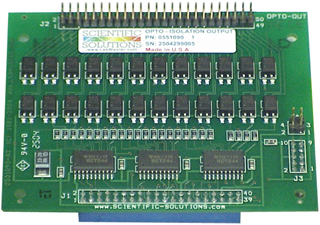
Scientific Solutions Opto OUT Module
The Scientific Solutions Opto Out Module provides Optical-Isolation for BaseBoard Digital Output signals and attaches directly to the BaseBoard
- Opto-Isolation Features:
- Optically Isolates the Digital Signals
- Eliminates 'ground difference' problems
- 5000 Volt Optical Isolation
- Transient Protection
- Increased drive capability for Digital I/O
- Protects Equipment from lighting strikes that propagate thru the digital signal lines
- Compact screw terminals available
- Cost effective method to add 24 channels of optical isolation to your Digital Output signals
Plug In Module - Opto Isolation Out
The Scientific Solutions Opto-Isolation OUT module is an optional module for use with the BaseBoard / ISA or BaseBoard / PCI digital I/O products. When used with the BaseBoard / ISA card, the module attaches directly to the PC card in the computer. When used with the BaseBoard / PCI product, the module is housed in the DeskTop unit. The BaseBoard / ISA and the BaseBoard / PCI DeskTop unit can each accommodate from 1 to 4 modules.
Although the module is designed for use with the Scientific Solutions BaseBoard products, it can be used as a stand-alone module with the 40 position socket header connector providing connections to the optical isolators input LED cathode (the anode has a pull-up resistor), and the 50 position pin header connector providing access to the isolators output transistor Collector (labed RT) and Emitter (labeled OUT).
Each module provides 24 bits of optically isolated digital OUTPUT signals providing 5000 volts of Optical Isolation, transient protection and increased drive capability. Each output line can support its own isolated load circuit up to 300 Volts. Additionally, each isolated output can handle increased current of up to 150 milliamps. This allows many output applications to be accomplished such as driving relays, solenoids, or LEDs, and to switch on/off power for contact closures, switches or other high voltage equipment. In medical or physiological environments, optical isolation provides additional protection, while protecting the computer power supply from switching transients.
There are two versions of the Scientific Solutions Opto-Isolation OUTPUT module
- Original thru-hole (TH) version
- Sold from 1981 until 2004
- Uses 4N32 Optical Device
- Newer surface-mount (SM) version
- Introduced in 2004 and is the current version
- Uses PS2532 Optical Device
- Has PowerTag Technology
- Smart Module with auto-identification circuitry
- Higher efficient Opto-coupler
- Direct replacement for TH version
We make a distinction between the two because they use different optical isolation devices and thus have slightly different specifications. The SM version can be used where ever the TH version is currently being used.
The SM version is part of Scientific Solutions Smart Module class of products. These modules incorporate Scientific Solutions PowerTag auto-identification features that allows them to be identified by a software query. This is helpful in that software can scan a BaseBoard system and determine the type and location of installed modules, (i.e. Input, Output or HS Polarity, etc.) and also can automatically check to be sure the digital ports are correctly configured (Input mode, Output mode, Strobed Handshaking, Bi-directional) to match the capabilities of the installed module.
Opto-Isolation Out Circuit
The Scientific Solutions Opto-Isolation Out Module used with the BaseBoard provides optical isolation between your computer and the device the module is connected to. The Opto-Isolation module converts a BaseBoard Digital Output to an optically isolated signal pair: RT and OUT. The signal pairs for each Digital Output is located on the module's 50 pin header.
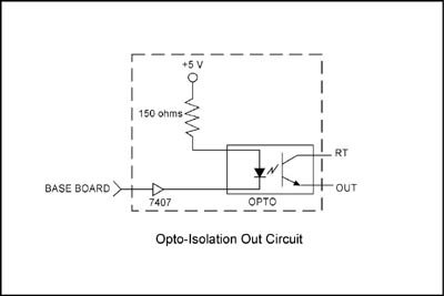
The above schematic diagram shows a single digital output line. The Opto-Isolator input LED is driven by the BaseBoard Digital Output signal. The resistor value shown in the diagram (sets the IF current) may be different on your actual module, depending on the model (TH or SM). Refer to the specifications listed later for the opto input LED forward current ( IF ).
A BaseBoard Digital output of logic 0 turns ON the opto input LED. The light from the LED shines upon the base of the opto's output transistor and this turns ON the opto's output transistor which then permits current to flow from the collector (RT pin) to the emitter (OUT pin).
A BaseBoard Digital output of logic 1 turns OFF the opto input LED. In this case there is no light from the LED and the base of the opto's output transistor remains dark and hence the output transistor is OFF and there is no RT to OUT current.
The previous described "optical link" between the opto's input LED and the output Transistor provides the optical isolation between input and output. Ground differences between the computer containing the BaseBoard and the circuits connected to the RT/OUT pins will have no effect, i.e. each side is fully isolated from the other.
The output terminals (RT and OUT) of the Opto-Isolation Module are the collector (RT) and Emitter (OUT) signals of the optical isolation device output transistor. Like any transistor it can be operated in the "saturated" region or the "linear" region depending on how it is used.
Typically when using the Opto module to connect to TTL logic devices, it is operating in the "saturated" mode and when using the Opto module to control an LED or Lamp it will be operating in the "linear" mode. This is because in the "saturated" mode, the output transistor (RT to OUT) can get close to 0 volts and provide decent sink current (on the order of 6ma) sufficient to provide a TTL logic low signal. Whereas in the "linear" region the RT to OUT voltage does not get low enough to be a TTL logic "low" signal, but can provide much more RT to OUT current (on the order of 60ma). It is a trade-off between Vce and Ice of the opto output transistor (Vce = Voltage from RT to OUT, and Ice is Current from RT to OUT).
Example: Using Opto-OUT to connect to a TTL logic Gate
When connecting the Opto-Isolation module to a "logic" circuit that is expecting TTL type of levels, the optical isolation device is used in the Vce saturation mode. The RT pin is generally connected to +5 volts thru a pull-up resistor and also connected to the input of a logic gate. The OUT pin is connected to the ground of the logic circuit.
In this example, the Opto-OUT is used to generate "TTL" types of logic signals. The following schematic shows a typical circuit. The RT pin (Emitter of the opto-out transistor) is connected thru a pull-up resistor to the isolated +5v supply (different from the +5 volts of the computer to provide isolation). This RT signal is fed into the input of a 74LS14 "Schmitt" trigger gate. The OUT pin (Collector of the opto-out transistor) is connected to the isolated Ground terminal of the circuit (different from the ground of the computer to provide isolation). Note that the LS14 device and the pull-up resistor is an example of a typical type of circuit and your circuit could be different depending upon your needs.
This example interface provides an inverted digital output.
- Logic 0 from BaseBoard produces logic 1 from 74LS14
- Logic 1 from BaseBoard produces logic 0 from 74LS14
The 74LS14 Schmitt Trigger output will sharpen the edges of the Opto-Isolator which has slow rise and fall times.

The +5v is on the Opto Module. The +5v_ISO is provided by the user
When connecting the Opto-Isolation module to a "logic" circuit that is expecting TTL type of levels, the optical isolation transistor is used in the Vce saturation mode.
When the BaseBoard digital output is low (logic '0') the opto input LED is ON and the output transistor is also ON. The Vce of the transistor (Collector to Emitter) voltage, i.e. RT to OUT voltage is low, typically 0.4 to 0.6 volts, and this presents a logic '0' to your circuit, which in this example is the input to the 74LS14 device. The 74LS14 is an inverter and presents a logic '1' at its output.
When the BaseBoard digital output is high (logic '1') the opto input LED is OFF and the output transistor is also OFF. The collector of the transistor (the RT pin) is pulled high thru the pullup and this is a logic '1' presented to your circuit, which in this example is the input to the 74LS14 device. The 74LS14 is an inverter and presents a logic '0' at its output.
It is important to note that the optical-isolation device is operating in the Saturation region of the transistor.
In saturation, the 4N32 device (used on the TH version of the module) has a maximum Ice current of about 6 mA.
In saturation, the PS2532 device (used on the SM version of the module) has a maximum Ice current of about 12 mA
The 4.7k resistor in the example schematic sets an Ice current of about 1 mA.
| BaseBoard Out = LO |
TH version | SM version |
|---|---|---|
| Rf (ohms) | 150 | 620 |
| Vrf (volts) | 3.43 | 3.75 |
| VF (volts) | 1.26 | 1.13 |
| IF (ma) | 23 | 6 |
| RL (ohms) | 4.7 | 4.7 |
| Vce (volts) | 0.40 | 0.67 |
| Ice (ma) | 0.98 | 0.93 |
| 74LS14 Logic Out |
1 | 1 |
| BaseBoard Out = HI |
TH version | SM version |
|---|---|---|
| Rf (ohms) | 150 | 620 |
| Vrf (volts) | 0 | 0 |
| VF (volts) | 0.51 | 0.35 |
| IF (ma) | 0 | 0 |
| RL (ohms) | 4.7 | 4.7 |
| Vce (volts) | 5.0 | 5.0 |
| Ice (ma) | 0 | 0 |
| 74LS14 Logic Out |
0 | 0 |
Example: Using Opto-Out to connect to an LED:
When connecting the Opto-Isolation module to a turn ON / OFF a LED or lamp, the optical isolation device is used in the Vce "linear" mode so that it will have sufficient electrical current (Ice) to illuminate the light. The RT pin is generally connected to the cathode of the LED, and the annode of the LED is connected to the voltage thru a current-limiting resistor. If instead of an LED you were powering "automotive" type incandescent panel lights, you would not need the current-limiting resistor. As a side note, an LED is generally a much better choice than an incandescent bulb since incandescent bulbs take a lot more current (very high "turn-on" cold starting current and also high operating current) and generate more heat. In any case, the OUT pin is connected to the ground of the light circuit.
In this example, the Opto is used to control (ON / OFF) an LED. The following schematic shows a typical circuit. The RT pin (Emitter of the opto-out transistor) is connected to the cathode of the LED. The annode of the LED is connected thru a 270 ohm resistor to the +5V_ISO supply. (different from the +5 volts of the computer if you desire isolation). This resistor provides current limiting to about 12ma which will typically provide good brightness from the LED. The OUT pin of the opto is connected to the return ground of the +5v_ISO (different from the ground of the computer is you desire isolation).
Logic 0 from Base Board turns ON the LED
Logic 1 from Base Board turns OFF the LED

The +5v is on the Opto Module. The +5v_ISO is provided by the user
| BaseBoard Out = LO |
TH version | SM version |
|---|---|---|
| Rf (ohms) | 150 | 620 |
| Vrf (volts) | 3.43 | 3.75 |
| VF (volts) | 1.26 | 1.13 |
| IF (ma) | 23 | 6 |
| RL (ohms) | 220 | 220 |
| Vce (volts) | 0.79 | 0.78 |
| Ice (ma) | 11.7 | 12 |
| LED | ON | ON |
| BaseBoard Out = HI |
TH version | SM version |
|---|---|---|
| Rf (ohms) | 150 | 620 |
| Vrf (volts) | 0 | 0 |
| VF (volts) | 0.51 | 0.35 |
| IF (ma) | 0 | 0 |
| RL (ohms) | 220 | 220 |
| Vce (volts) | 3.89 | 3.92 |
| Ice (ma) | 0 | 0 |
| LED | OFF | OFF |
Example: Using Opto-Out to connect to an Incandescent Lamp:
When connecting the Opto-Isolation module to a turn ON / OFF an incandescent lamp, the optical isolation device is used in the Vce "linear" mode so that it will have sufficient electrical current (Ice) to illuminate the light. The RT pin is generally connected to one side of the lamp and the other side of the lamp is connected to the voltage the lamp requires. As previously noted, an LED is generally a much better choice than an incandescent bulb since incandescent bulbs take a lot more current (very high "turn-on" cold starting current and also high operating current) and generate more heat. In any case, the OUT pin is connected to the ground of the light circuit.
In this example, the Opto is used to control (ON / OFF) an automotive incandescent LED. The following schematic shows a typical circuit. The RT pin (Emitter of the opto-out transistor) is connected to one side of the lamp and the other side is connected to +12 volts. The OUT pin of the opto is connected to the return ground of the +12v supply.
Logic 0 from Base Board turns ON the LED
Logic 1 from Base Board turns OFF the LED
The +5v is on the Opto Module. The +12v is provided by the user
| BaseBoard Out = LO |
TH version | SM version |
|---|---|---|
| Rf (ohms) | 150 | 620 |
| Vrf (volts) | 3.43 | 3.75 |
| VF (volts) | 1.26 | 1.13 |
| IF (ma) | 23 | 6 |
| RL (ohms) | lamp | lamp |
| Vce (volts) | 0.93 | 0.90 |
| Ice (ma) | 60 | 60 |
| Lamp | ON | ON |
| BaseBoard Out = HI |
TH version | SM version |
|---|---|---|
| Rf (ohms) | 150 | 620 |
| Vrf (volts) | 0 | 0 |
| VF (volts) | 0.51 | 0.35 |
| IF (ma) | 0 | 0 |
| RL (ohms) | lamp | lamp |
| Vce (volts) | 12 | 12 |
| Ice (ma) | 0 | 0 |
| Lamp | OFF | OFF |
Vce / Ice Calculation Notes for Original Design using 4N32 device:
(1). The Rf value is 150 ohms.
(2). The Opto-Isolator input LED drops about 1.5v, meaning that 3.5v is across the 150ohm resistor. This provides 3.5v / 150 = 23mA of current sink by the 7407 device. The current thru the LED is called the forward current and is designated IF
(3). The Opto-Isolator Emitter-Collector Current (designated by ICE) is calculated by:
ICE = (IF) * (CTRnormalized) * (CTRcorrection) where the CTRnormalized
for the 4N32 is 500% when operating in the linear (non-saturated) region
Referring to the 4N32 specifications, and the Output Current vs. Input
Current graph we see that for 10ma Input that the CTRcorrection =
1. This graph is normalized for IF=10ma and Vce = 5 volts (linear
region).
So for 10ma,
ICE = (IF) * (CTRnorm)* (CTRcorr)
ICE = 10ma * (500%) * 1
ICE = 50ma
This means that for an IF of 10ma the maximum ICE would be 50ma.
However, the Opto-Isolator Module has an IF of 23ma (set by the 150ohm resistor)
Referring to the 4N32 specifications, again the Output Current vs.
Input Current graph we see that for 23ma Input the CTRcorrection = 0.69
So for 23ma,
ICE = (IF) * (CTRnorm) * (CTRcorr)
ICE = 23ma * (500%) * 0.69
ICE = 80ma
This means that the ICE could be as high as 80ma.
Note that this 80ma current is when the transistor is operating in the linear region.
The 4N32 has a total power dissipation of 250mwatts (including input and output power dissipation).
The input power dissipation is (IF)*(VF) = 23ma * 1.5v = 35mw
This leaves 250mw - 35mw = 215mw for the output power dissipation, i.e. (ICE) * (VCE)
Assuming Vce = 2.5 volts and with Pout = 215mw, then ICE calculated = Pout / Vce = 215mw / 2.5v = 80ma
VCEsat = 1.2 volts and with Pout = 215mw, then ICE calculated = Pout/Vce = 215mw / 1.2v = 180ma
However, the ICE max has already been set to 80ma via the 150ohm resistor which sets the IF, which in turn sets the ICE.
The VCE / ICE is determined by the IF=23ma, the Current-transfer-ration ( Ice / If), the total power dissipation of the package, and the operating mode of the device (linear or saturation).
Vce / Ice Calculation Notes for Original Design using PS2532 device:
(1). The Rf value is 620 ohms.
(2). The Opto-Isolator input LED drops about 1.25v, meaning that 3.75v is across the 620ohm resistor. This provides 3.75v / 620 = 6mA of current sink by the buffer device. The current thru the LED is called the forward current and is designated IF
(3). The Opto-Isolator Emitter-Collector Current (designated by ICE) is calculated by:
ICE = (IF) * (CTRnormalized) * (CTRcorrection) where the CTRnormalized
for the PS2532 is about 2500% (from the data sheet of the PS2532) when
IF=6 ma and Vce = 2 volts which is operating in the linear
(non-saturated) region
Referring to the PS2532 specifications, and the Output Current vs. Input
Current graph we see that for 10ma Input that the CTRcorrection =
1. This graph is normalized for IF=10ma and Vce = 5 volts (linear
region).
So for 10ma,
ICE = (IF) * (CTRnorm)* (CTRcorr)
ICE = 6ma * (2500%) * 1
ICE = 150ma
This means that for an IF of 6ma the maximum ICE would be 150ma.
Note that this 150ma current is when the transistor is operating in the linear region.
The PS2532 has a total power dissipation of 150mwatts for the input diode and 300 mwatts for the output transistor.
The input power dissipation is (IF)*(VF) = 6ma * 1.25v = 7.5mw which is well below the 150mw maximum.
The 300 mw is the power dissipation of (ICE) * (VCE)
Assuming Vce = 2 volts and with Pout = 300mw, then ICE calculated =
Pout / Vce = 300mw / 2v = 150ma
Note that this 150ma happens to be the same as the maximum current
available which is set by the IF and the CTR of the device.
The VCE / ICE is determined by the IF=6ma, the Current-transfer-ration ( Ice / If), the total power dissipation of the package, and the operating mode of the device (linear or saturation).
It is recommended that you refer to the data sheets for the opto-isolation devices used on the module for further understanding of their characteristics.
 Technical Specifications
| Module | Thru-Hole Design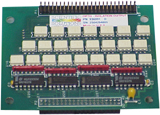 |
Surface-Mount Design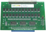 |
|---|---|---|
| Isolator Type | 4N32 | PS2532 |
| Input Diode Current, If | 23 mA | 5 mA |
| Collector Emitter Voltage (Vce) RT pin to OUT pin (Maximum Forward voltage) |
30 Volt | 300 Volt |
| Vce Saturation Voltage (maximum) | 1.0 Volt | 1.0 Volt |
| Output Current (Ice) RT pin to OUT pin (Maximum Forward Current when linear, non-saturated) |
80 mA | 150 mA |
| Emitter Collector Voltage (Vec) OUT pin to RT pin (Maximum Reverse Voltage) |
5 Volt | 6 Volt |
| Isolation Maximum (Vin / Vout) | 2500 Volt | 5000 Volt |
| Switching Rise Time Maximum | 100 uSec | 100 uSec |
| Switching Fall Time Maximum | 100 uSec | 100 uSec |
| Operating Temperature | 0º to 70º Celsius |
|---|---|
| Storage Temperature | -25º to +85º Celsius |
| Relative Humidity | To 95% non-condensing |
| Agency Approvals | Class A, CE-Mark |
Opto-Isolation OUT 50 Position Pin Header Connector
This 50 position pin header connector provides access to the opto-isolation Collector and Emitter outputs
RT is the Collector
OUT is the Emitter
| NC | C4 OUT |
A1 OUT |
A2 OUT |
A0 OUT |
A4 OUT |
A3 OUT |
C6 OUT |
A5 OUT |
C5 OUT |
A7 OUT |
C7 OUT |
A6 OUT |
C3 OUT |
C0 OUT |
C1 OUT |
B1 OUT |
B0 OUT |
C2 OUT |
B3 OUT |
B2 OUT |
B5 OUT |
B6 OUT |
B4 OUT |
B7 OUT |
| 2 | 4 | 6 | 8 | 1 | 12 | 14 | 16 | 18 | 20 | 22 | 24 | 26 | 28 | 30 | 32 | 34 | 36 | 38 | 40 | 42 | 44 | 46 | 48 | 50 |
| 1 | 3 | 5 | 7 | 9 | 11 | 13 | 15 | 17 | 19 | 21 | 23 | 25 | 27 | 29 | 31 | 33 | 35 | 37 | 39 | 41 | 43 | 45 | 47 | 49 |
| NC | C4 RT |
A1 RT |
A2 RT |
A0 RT |
A4 RT |
A3 RT |
C6 RT |
A5 RT |
C5 RT |
A7 RT |
C7 RT |
A6 RT |
C3 RT |
C0 RT |
C1 RT |
B1 RT |
B0 RT |
C2 RT |
B3 RT |
B2 RT |
B5 RT |
B6 RT |
B4 RT |
B7 RT |
Opto-Isolation IN 40 position socket Header Connector
This 40 position header connector provides access to the input LED cathode. The LED anode has a pull-up resistor. The input LED optically couples to the opto-transistors Base
The Gnd and the +5 are the positive 5 volt and respective ground connection for the output side of the Opto-Isolators
The NC are reserved NO Connection positions.
| A0 | A1 | A2 | A3 | A4 | A5 | A6 | A7 | C5 | C7 | C1 | C3 | Gnd | Gnd | Gnd | NC | NC | +5 | NC | Gnd |
| 2 | 4 | 6 | 8 | 10 | 12 | 14 | 16 | 18 | 20 | 22 | 24 | 26 | 28 | 30 | 32 | 34 | 36 | 38 | 40 |
| 1 | 3 | 5 | 7 | 9 | 11 | 13 | 15 | 17 | 19 | 21 | 23 | 25 | 27 | 29 | 31 | 33 | 35 | 37 | 39 |
| Gnd | NC | +5 | NC | NC | Gnd | Gnd | Gnd | C4 | C6 | C0 | C2 | B0 | B1 | B2 | B3 | B4 | B5 | B6 | B7 |
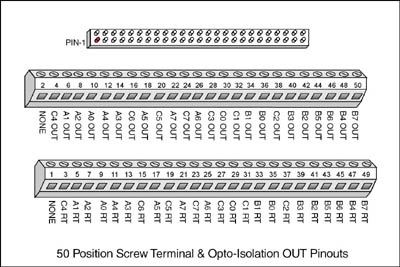
Opto Isolation Out 50 pin Screw Terminal (Option)
When you have an Opto-Isolation OUT module installed, then you will have 50pin connectors on the BaseBoard. You can connect a 50 position screw terminal to this connector. The Opto-Isolated Digital OUTPUT signals are then connected to the screw terminals and are transmitted to the Opto-Isolation Module via a ribbon cable. The ribbon cable is connected between the screw terminal and the Modules 50pin Opto-Isolation connector. The striped edge of the ribbon cable connects to Pin 1.
Specifications subject to change without notice.
Scientific Solutions liability, trademarks, and export notices apply.
Copyright © 1972-2025 Scientific Solutions - All rights reserved.