Scientific Solutions ® Inc.
Opto-Isolation INPUT Module
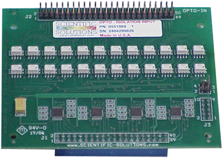
Scientific Solutions Opto IN Module
The Scientific Solutions Opto In Module provides Optical-Isolation for BaseBoard Digital Input signals and attaches directly to the BaseBoard
- Opto-Isolation Features:
- Optically Isolates the Digital Signals
- Eliminates 'ground difference' problems
- 2500 Volt Isolation
- Transient Protection
- Increased drive capability for Digital signals
- Protects Equipment from lighting strikes the propagate thru the digital signal lines
- Compact screw terminals available
- Cost effective method to add 24 channels of optical isolation to your Digital Input signals
Plug In Module - Opto Isolation In
The Scientific Solutions Opto-Isolation IN module is an optional module for use with the BaseBoard / ISA or BaseBoard / PCI digital I/O products. When used with the BaseBoard / ISA card, the module attaches directly to the PC card in the computer. When used with the BaseBoard / PCI product, the module is housed in the DeskTop unit. The BaseBoard / ISA and the BaseBoard / PCI DeskTop unit can each accommodate from 1 to 4 modules.
Although the module is designed for use with the Scientific Solutions BaseBoard products, it can be used as a stand-alone module with the 40 position socket header connector providing connections to the optical isolators output Collector / Emitter signals (collector signals have a pull-up resistor and pass thru a TTL gate; emitter signals are connected to the common ground), and the 50 position pin header connector providing access to the isolators input LED (essentiall the LED that photocouples to the transistor base).
Each module provides 24 bits of optically isolated digital INPUT signals providing 2500 volts of Optical Isolation, transient protection and increased voltage capability. Each input line can support input voltages higher than the +5v TTL levels of typical digital signals. This allows many input applications to be accomplished such as monitoring of relays, contacts or switches; and monitoring the state of other high voltage equipment. In medical or physiological environments, optical isolation provides additional protection, while protecting the computer power supply from switching transients.
There are two versions of the Scientific Solutions Opto-Isolation INPUT module
- Original thru-hole (TH) version
- Sold from 1981 until 2004
- Uses 4N25 Optical Device.
- Newer surface-mount (SM) version
- Introduced in 2004 and is the current version
- Uses MOC217-M Optical Device
- Has PowerTag Technology
- Smart Module with auto-identification circuitry
- Higher efficient Opto-coupler
- Direct replacement for TH version
We make a distinction between the two because they use different optical isolation devices and thus have slightly different specifications. The SM version can be used where ever the TH version is currently being used.
The SM version is part of Scientific Solutions Smart Module class of products. These modules incorporate Scientific Solutions PowerTag auto-identification features that allows them to be identified by a software query. This is helpful in that software can scan a BaseBoard system and determine the type and location of installed modules, (i.e. Input, Output or HS Polarity, etc.) and also can automatically check to be sure the digital ports are correctly configured (Input mode, Output mode, Strobed Handshaking, Bi-directional) to match the capabilities of the installed module.
Opto Isolation In Circuit
The Scientific Solutions Opto-Isolation In Module used with the BaseBoard provides optical isolation between your computer and the device the module is connected to. The Opto-Isolation module converts an optically isolated signal pair, IN and RT, to a BaseBoard Digital Input. The signal pairs for each Digital Input is located on the module's 50 pin header.
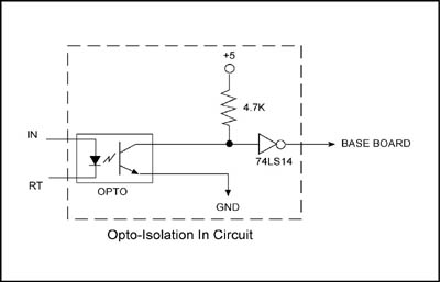
The above schematic diagram shows a single digital input line. The Opto-Isolator input LED is driven by the IN and RT signals.
When sufficient current flows from the IN to the RT pin, the opto input LED is turned ON. The light from the LED shines upon the base of the opto's output transistor and this turns ON the opto's output transistor which pulls the input to the 74LS14 low, which in turn provides a Digital Input logic level of '1' to the BaseBoard.
When there is not enough current flowing from the IN to the RT pin, the opto input LED is OFF. In this case there is no light from the LED and the base of the opto's output transistor remains dark and hence the output transistor is OFF which allows the input to the 74LS14 to be pulled high thru the pull-up resistor, which in turn provides a Digital Input logic level of '0' to the BaseBoard.
The previous described "optical link" between the opto's input LED and the output Transistor provides the optical isolation between input and output. Ground differences between the computer containing the BaseBoard and the circuits connected to the IN/RT pins will have no effect, i.e. each side is fully isolated from the other.
The input terminals (IN and RT) of the Opto-Isolation Module are the annode (IN) and cathode (RT) signals of the optical isolation device input LED. Like any LED, it requires current limiting to avoid damage, and normally there is some type of current limiting resistor that is required, and supplied by the user since its value depends upon the circuit connected to the Opto Input. Also, like any LED there is an amount of current that is required in order to light the LED - referred to as the Forward Current, and signified by the variable IF.
Example: Connecting a TTL logic Gate to Opto-IN
In this example, the Opto-IN is used to accept "TTL" types of logic signals. The following schematic shows a typical circuit. The IN pin (annode of opto input LED) is connected thru a pull-up resistor to the isolated +5v supply (different from the +5 volts of the computer to provide isolation). This RT signal is connected to the output of a TTL gate that can sink 12ma of current. The sink current is determined from the value of the pull-up resistor. The LED will have a voltage drop across it of about 1.15 volts, leaving 3.85 volt drop across the 330 ohm resistor which limits the current to 3.85 volts / 330 ohm = 12 ma.
Opto-In Typical User Added Interface:
- Logic 0 from an external device produces a logic 0 to the BaseBoard
- Logic 1 from an external device produces a logic 1 to the BaseBoard
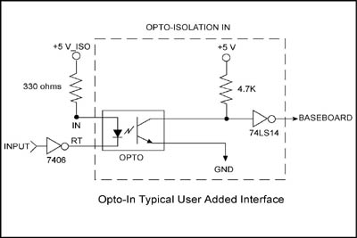
Opto In with Typical User Added Interface for TTL signals
In this example the output of a logic gate (7406 shown) is connected to the RT pin of the Opto module. When the TTL buffer has a logic '0' (typically 0 to 0.8volts) on the RT pin, current flows from the IN to the RT and turns on the LED. In this case the TTL buffer is "sinking" the 12ma of current. When the TTL buffer has a logic '1' (typically 2.8 to 5volts) on the RT pin, current does not flow and the LED is off.
Another method would be to connect the RT to ground, and connect the gate to the IN pin - however this is generally not as good as the method shown here. The method shown here is generally better because TTL gates typically can "sink" more current than they can "source".
Example: Monitoring a 15 volt switch with Opto-IN
Sometimes you may want to monitor a SPDT switch which toggles between ground and +15 volts. In this example, the one throw of the switch is connected to ground, while the other throw of the switch is connected thru a "current limiting resistor" to the +15 volts. The current limiting resistor could be selected assuming you want 10ma going thru the Opto input when the switch is to the +15 volt position. The value would be (15 - 1.5)/10 ma = 1.35 Kohm. Using an easy-to-obtain value of 1 Kohm would be a good choice and provide 13.5ma of current, more than sufficient to illuminate the input LED, yet much less than the 60 ma maximum. The less current, the less heat and the smaller your +15 volt supply has to be.
Note: If you use both the TH and the SM version of the Opto module in your system, you may want to design around the TH version so you can swap between either one. If you only use the SM version, then you can save on heat and power by using less electrical current in your design.
 Technical Specifications
| Module | Thru-Hole Design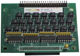 |
Surface-Mount Design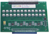 |
|---|---|---|
| Isolator Type | 4N25 | MOC217-M |
| Input Forward Voltage IN pin to RT pin (Maximum Forward Voltage Drop across input diode) |
1.5 Volts | 1.3 Volts |
| Minimum Input Current IN pin to RT pin (Minimum Forward Input Current to turn opto "on") |
10 mA | 2 mA |
| Maximum Input Current IN pin to RT pin (Maximum Forward Input Current before damage) |
80 mA | 60 mA |
| Maximum Input Reverse Voltage RT pin to IN pin (Maximum Reverse Input Voltage before damage) |
3 Volts | 6 Volts |
| Isolation Maximum | 2500 Volts | 2500 Volts |
| Switching Times | - | - |
| Rise Time Maximum | 3 uSec | 3 uSec |
| Fall Time Maximum | 3 uSec | 3 uSec |
| Operating Temperature | 0º to 70º Celsius |
|---|---|
| Storage Temperature | -25º to +85º Celsius |
| Relative Humidity | To 95% non-condensing |
| Agency Approvals | Class A, CE-Mark |
Opto-Isolation IN 50 Position Pin Header Connector
This 50 position pin header connector provides access to the opto-isolation input LED the optically couples to the opto-transistors base.
IN is the LED anode
RT is the LED cathode
| NC | A0 RT |
A2 RT |
A1 RT |
A3 RT |
A4 RT |
A5 RT |
C5 RT |
C7 RT |
C6 RT |
A6 RT |
A7 RT |
C4 RT |
C1 RT |
B1 RT |
C3 RT |
B0 RT |
C2 RT |
C0 RT |
B5 RT |
B2 RT |
B6 RT |
B3 RT |
B7 RT |
B4 RT |
| 2 | 4 | 6 | 8 | 10 | 12 | 14 | 16 | 18 | 20 | 22 | 24 | 26 | 28 | 30 | 32 | 34 | 36 | 38 | 40 | 42 | 44 | 46 | 48 | 50 |
| 1 | 3 | 5 | 7 | 9 | 11 | 13 | 15 | 17 | 19 | 21 | 23 | 25 | 27 | 29 | 31 | 33 | 35 | 37 | 39 | 41 | 43 | 45 | 47 | 49 |
| NC | A0 IN |
A2 IN |
A1 IN |
A3 IN |
A4 IN |
A5 IN |
C5 IN |
C7 IN |
C6 IN |
A6 IN |
A7 IN |
C4 IN |
C1 IN |
B1 IN |
C3 IN |
B0 IN |
C2 IN |
C0 IN |
B5 IN |
B2 IN |
B6 IN |
B3 IN |
B7 IN |
B4 IN |
Opto-Isolation IN 40 position socket Header Connector
This 40 position socket header connector povides access to the Emitter and Collector outputs of the Opto-Isolators.
The Collector signals have a pull-up resistor and pass thru a TTL gate
The Emitter signals are connected to the common ground
The Gnd and the +5 are the positive 5 volt and respective ground connection for the output side of the Opto-Isolators
The NC are reserved NO Connection positions.
| A0 | A1 | A2 | A3 | A4 | A5 | A6 | A7 | C5 | C7 | C1 | C3 | Gnd | Gnd | Gnd | NC | NC | +5 | NC | Gnd |
| 2 | 4 | 6 | 8 | 10 | 12 | 14 | 16 | 18 | 20 | 22 | 24 | 26 | 28 | 30 | 32 | 34 | 36 | 38 | 40 |
| 1 | 3 | 5 | 7 | 9 | 11 | 13 | 15 | 17 | 19 | 21 | 23 | 25 | 27 | 29 | 31 | 33 | 35 | 37 | 39 |
| Gnd | NC | +5 | NC | NC | Gnd | Gnd | Gnd | C4 | C6 | C0 | C2 | B0 | B1 | B2 | B3 | B4 | B5 | B6 | B7 |
Opto-Isolation In 50 pin Screw Terminal Option
When you have an Opto-Isolation IN module installed in the DeskTop Unit, then you will have 50pin connectors on the front of the DeskTop Unit. You can connect a 50 position screw terminal to the front panel connector(s). The Opto-Isolated Digital I/O signals are then connected to the screw terminals and are transmitted to the Opto-Isolation Module via a ribbon cable. The ribbon cable is connected between the screw terminal and the DeskTop front panel 50pin Opto-Isolation connector. The striped edge of the ribbon cable connects to Pin 1.
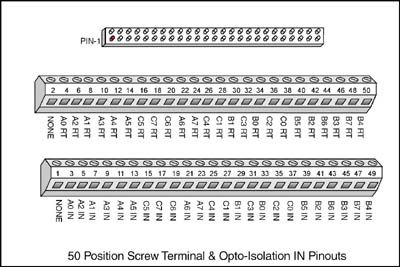
Scientific Solutions Opto IN Screw Terminal Pin Out
Specifications subject to change without notice.
Scientific Solutions liability, trademarks, and export notices apply.
Copyright © 1972-2025 Scientific Solutions - All rights reserved.