Scientific Solutions ® Inc.
BaseBoard ® ADC1614 PGL Module
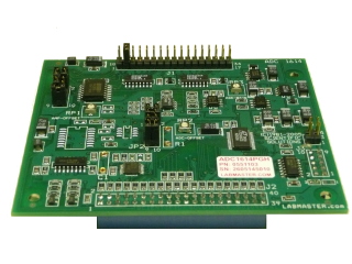
Scientific Solutions ADC1614 PGL Analog Input Module
The BaseBoard ADC1614 PGL Module provides 16 Analog Inputs and attaches directly to the BaseBoard.
- For use with the BaseBoard / PCI Digital I/O products
- Analog Input Features:
- 14 bit resolution
- Analog Input Software Programmable Gain:
- 1, 10, 100
- Analog Input Range:
- -100mV to +100mV, -1.0v to +1.0v, -10v to +10v
- 0 to +100mV, 0 to +1v, 0 to +10v
- Installs inside the BaseBoard PCI DeskTop unit
- connects to 40 pin header of BaseBoard product
- Provides 16 Analog Inputs to your BaseBoard product
- provides a 34 pin header for Analog Input signals
- each Analog Input is paired up with a ground connection
- Compact screw terminals available
- Cost effective method to add Analog Inputs to your BaseBoard product
- Scientific Solutions PowerTag® compliant
- LabPac software automatically identifies and configures the module
- Multiple Modules can be installed on a BaseBoard product
- Up to 192 Analog Outputs from a single BaseBoard / PCI card
Plug In Module - ADC1614 PGL
The Scientific Solutions ADC1614 PGL module is an optional module for use with the BaseBoard / PCI digital I/O products. When used with the BaseBoard / PCI product, the module is housed in the DeskTop unit. The BaseBoard / PCI DeskTop unit can accommodate from 1 to 3 ADC1614 PGL modules
The ADC1614 PGL module provides 16 Analog Input channels. Analog signals in the ±10 volt range down to the ±0.10 volt range (±100mV) are digitized by an Analog-to-Digital Converter (ADC). Designed to deliver flexible data, the analog input can be configured for unipolar or bipolar input ranges. A variable software controlled gain amplifier at the input to the sample and hold circuit allows the input range to vary. With software controlled gains of 1, 10, 100 the ADC1614 PGL provides Unipolar input ranges from 0 to +100mV volts up to 0 to +10 volts and Bipolar input ranges from ±100mV up to ±10 volts.
The ADC1614 PGL uses a 14-bit resolution ADC. This means that for the 0 to +100mV range, the ADC can measure analog input changes as small as 6uV and for the -10v to +10v range the ADC can measure analog input changes as small as 1.22mv, up to a maximum of +10 volts.
The PGL stands for "Programmable Gain Low" which is a feature that permits you to change the gain on a channel-by-channel basis under software control. It is intended for "Low" level analog signals since the gains are relatively high, hence the name PGL
The ADC1614 PGL module requires an Analog Power Supply (APS) Module to also be installed in the BaseBoard. The APS supplies the ADC1614 PGL analog circuits with a regulated low-noise power source. A BaseBoard can accommodate from 1 to 4 add-on modules. With one position used for the Analog Power Supply, this leaves three other positions to be used for other moduels. You can add any combination of other modules that you want (Analog Input, Analog Output, Opto-isolated Digital Input or Output, etc).
If you add three ADC1614 PGL modules, then you have 48 Analog Input channels per DeskTop unit. Daisy chain up to four BaseBoard DeskTop units to a single PCI card and you can get 192 Analog Inputs using ADC1614 modules. Add four BaseBoard / PCI cards to a single computer and you have 768 Analog Inputs available!
Configuring the ADC1614 PGL
This module is Scientific Solutions PowerTag compliant, meaning that when this module is attached to a product, such as the BaseBoard / PCI that also has PowerTag technology, the BaseBoard product can query the module and obtain characteristic information, such as the module type, the number of channels, voltage range, etc. This permits auto-configuration of the product without having to prompt the user for this information.
The control and operation of the ADC1614 PGL module is fully supported by
Scientific Solutions device drivers and LabPac function library.
 Technical Specifications
| Channel Count | 16 |
|---|---|
| Resolution | 14 bit |
| Maximum sampling rate | 150khz |
| Software programmable Gain | 1, 10, 100 |
| Analog Input Range (software Selectable) | 0v to +0.100v (unipolar, 6.1uV / count) 0 to +1.0v (unipolar, 61uV / count) 0 to +10v (unipolar, 610uV / count) -0.100v to +0.100v (bipolar, 12.2uV / count) -1.0v to +1.0v (bipolar, 122uV / count) -10v to +10v (bipolar, 1.22mv / count |
| Smallest Input Change | 6.1uV (0v to +100mV range) to 1.22mv (-10v to +10v range) |
| Quantizing Error | ±1/2 LSB max over temp. range |
| Integral non-linearity | ±1/2 LSB max over temp. range |
| Differential non-linearity | ±1/2 LSB max over temp. range |
| Monotonicity | Guaranteed over temp. range |
| Coef. of Linearity | 3ppm / ºC |
| Coef. of Diff. Linearity | 3ppm / ºC |
| Digital Data and Control Interface | BaseBoard connection |
|---|---|
| Number of Modules per BaseBoard PCI system | From 1 to 3 per DeskTop unit Maximum 4 Desktop units for a total of 12 Modules (192 Analog Input Channels) |
| Input Header Connector on Module | 40 position socket header, dual row of 20, 1/10" pin spacing |
| Output Header Connector on Module | 34 position Pin Header, dual row 17 pins, 1/10" pin spacing |
| Dimensions | 3.875" x 3.200" (98mm x 81mm) |
| Operating Temperature | -40º to +100º Celsius |
|---|---|
| Storage Temperature | -40º to +125º Celsius |
| Relative Humidity | To 95% non-condensing |
| Agency Approvals | Class A, CE-Mark |
ADC1614 Analog Input 34 Position Pin Header Connector
This 34 position pin header connector provides access to the analog input signals and grounds.
The NC are reserved NO Connection positions.
| Gnd | Gnd | Gnd | Gnd | Gnd | Gnd | Gnd | Gnd | Gnd | Gnd | Gnd | Gnd | Gnd | Gnd | Gnd | Gnd | Gnd |
| 18 | 19 | 20 | 21 | 22 | 23 | 24 | 25 | 26 | 27 | 28 | 29 | 30 | 31 | 32 | 33 | 34 |
| 1 | 2 | 3 | 4 | 5 | 6 | 7 | 8 | 9 | 10 | 11 | 12 | 13 | 14 | 15 | 16 | 17 |
| ADC 1 |
ADC 2 |
ADC 3 |
ADC 4 |
ADC 5 |
ADC 6 |
ADC 7 |
ADC 8 |
ADC 9 |
ADC 10 |
ADC 11 |
ADC 12 |
ADC 13 |
ADC 14 |
ADC 15 |
ADC 16 |
NC |
ADC1614 Analog Input 40 position socket Header Connector
This 40 position socket header connector povides access to the BaseBoard Digital I/O lines that control and send data to the Analog-to-Digital Converters.
The NC are reserved NO Connection positions.
| A0 | A1 | A2 | A3 | A4 | A5 | A6 | A7 | C5 SDI |
C7 RST |
C1 CS1 |
C3 CS3 |
Gnd | Gnd | Gnd | APS N15 |
APS P15 |
+5 | APS AGND |
Gnd |
| 2 | 4 | 6 | 8 | 10 | 12 | 14 | 16 | 18 | 20 | 22 | 24 | 26 | 28 | 30 | 32 | 34 | 36 | 38 | 40 |
| 1 | 3 | 5 | 7 | 9 | 11 | 13 | 15 | 17 | 19 | 21 | 23 | 25 | 27 | 29 | 31 | 33 | 35 | 37 | 39 |
| Gnd | APS AGND |
+5 | APS P15 |
APS N15 |
Gnd | Gnd | Gnd | C4 CLK |
C6 LREG |
C0 CS0 |
C2 CS2 |
B0 | B1 | B2 | B3 | B4 | B5 | B6 | B7 |
ADC1614 Screw Terminal Option
When you have an ADC1614 module installed in the DeskTop Unit, then you will have 34 pin connectors on the front of the DeskTop Unit. You can connect a 34 position screw terminal to the front panel connector(s). The Analog Input signals are then available to the screw terminals. A 34 position ribbon cable is used to connect between the BaseBoard unit and the screw terminal unit. Typically, the striped edge of the ribbon cable connects to Pin 1 of the connectors.
Specifications subject to change without notice.
Scientific Solutions liability, trademarks, and export notices apply.
Copyright © 1972-2025 Scientific Solutions - All rights reserved.