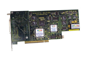
Scientific Solutions ® Inc.
LabMaster ® PRO PCI
| Product Description
|
LabMaster PRO provides true 16 bit 333Khz A/D
with up to 256 channels using high-performance Bus Mastering PCI!
Multiple cards can be synchronized for 1000 analog input channels!
The LabMaster PRO combines the features of several high-performance products onto an advanced PCI card. With a full range of features such as Analog Input, Analog Output, Digital I/O and Precision Timer/Counters - the LabMaster PRO provides the functionality required for a wide range of test and measurement applications. Great care is taken in the design and manufacturing of the LabMaster PRO to insure a quality product that provides accuracy and stability for demanding applications. Its unique features, rugged design and reliability make it ideal for acquiring and analyzing data in industrial, scientific, and educational fields. Whether your applications are laboratory research, product development or production testing, the LabMaster PRO is up to the task and should provide you with years of reliable and trusted service. Scientific Solutions has been providing data acquisition products since 1974. The LabMaster products from Scientific Solutions are the longest selling and supported PC based data acquisition products in the world. First introduced in 1981, they created the PC data acquisition market and were the world's first add in products of any type for the IBM PC. The LabMaster PRO continues with this fine tradition. |
 Product
Description
Product
Description
The Lab Master PRO PCI brings the power, performance, and flexibility needed to handle the toughest assignments in engineering and scientific research. Designed for today's faster PCI systems, the Lab Master PRO delivers the advanced features you expect in a data acquisition interface, with the precision of current technology and ease of use of an all software configurable interface.
Lab Master PRO is an advanced data acquisition product. It features high speed analog-to-digital conversion, sample FIFO buffering, coordinated simultaneous ADC and DAC capabilities, programmable gain amplifiers, high speed counters/timers and digital I/O on a single card. Complete solutions include the Lab Master card, cabling, and desktop connector termination unit.
The 16-bit analog to digital converter (ADC) handles 16 to 256 input lines at rates up to 333,000 samples/second. Precision software programmable gain amplifiers handle voltage ranges between ±l00mV and ±10V. Two independent 16-bit digital to analog converters (DAC) supply a ±10V output range. Five 16-bit precision counters can time intervals with 250nsec. resolution or count events up to 6MHz. Digital I/O lines (8 input/16 output) connect to switches, LEDs, relays, etc. Connections are made using a single high density connector with included RF-shielded cable.
Our
Solution Includes
- Lab Master PRO PCI Interface - Data Acquisition & Control interface for inside the PC
- 1.5 meter double shielded cable
- Desktop Unit (several versions available)
- Software Drivers
Key Features
- True 16-bit Analog-to-Digital and Digital-to-Analog Conversion.
- True simultaneous sample-and-hold
- 16 Analog input channels expandable to 256.
- High data rates (333,000 samples/second) to provide maximum speed and versatility.
- Dual High-Speed (500KHz) Analog Outputs.
- Five 16-bit High Resolution Cascadable Timer/Counters.
- Digital I/O lines - 8 in, 8 out, 8 FIFO controlled for digital pattern generation or digital In/Out expansion.
- Digital output coordinated with DACs (can be used with PCI Bus Mastering)
- Provisions for digital I/O & Analog input channel expansion
- Precision Software programmable gain amplifiers.
- High-performance ADC Channel / Gain Array with auto-increment allows automatic sampling of the analog inputs in any order with different gains at full speed.
- Dedicated on-board FIFO memory for high-performance acquisition and waveform generation with reduced CPU overhead
- On-board timers provide timed, simultaneous ADC and DAC updates.
- Continuous DAC output with on-board memory buffering and PCI Bus Mastering - excellent for clean waveform generation!
- Timed, simultaneous DAC updates ("no-jitter" analog outputs)
- Coordinated ADC and DAC using simultaneous and concurrent 32-bit PCI Bus Mastering (allows for simultaneous "record & playback")
- Multiple active hardware interrupt sources
- Advanced Surface mount technology for high reliability
- Physical small size (9" length) with narrow height for newer slim line computers.
- Advanced ESD protection against damage by human static discharge or lightning strikes.
Applications
- Energy Management
- Chromatography
- BioMedical (neuron stimulation, muscular stress)
- Psychology (infant stimulation, stimulus/response, interval timing, Galvanic skin response)
- Process Automation (relay control, stepper motor control, timing/counting, die cutting monitor)
- Test and Measurement (PC board tester, particle counter, component solderability determination)
Functional
Description
The LabMaster PRO installs into a PCI expansion slot of a computer. A single high-density connector is provided for easy access to all input and output lines. The LabMaster PRO is capable of multiple concurrent Bus Master operations for optimal PCI data performance. Designed for maximum flexibility, all features on the LabMaster PRO are software programmable.
Analog-to-Digital
Conversion (ADC)
The Analog-to-Digital converter (ADC) is a 16-bit successive approximation converter with a 3µSec. conversion time for a maximum throughput of 333Khz. The analog inputs (single-ended or true-differential) pass thru a programmable, precision gain amplifier prior to the analog-to-digital conversion. Examples of analog inputs are: Temperature, Flow, Displacement, Voltage, Current, Acceleration, Velocity, Level, Pressure, Moisture, and Humidity.
A conversion can be started by a software command, a trigger signal from one of the on-board precision timer/counters, a rising edge from an external source, self-triggered by the end of the last conversion, or by using the on-board analog compare. An on-board channel/gain memory allows any combination of channels and gains with complete auto-sequencing and burst mode performance. Channels can be selected for conversion one at a time or as a set. The software enabled auto-scan feature automatically increments the channel number with each conversion. Both the starting and ending channel in the sequence are software selectable.
Converted data is transferred to dedicated on-board sample memory buffers. The buffers permit full-speed operation under non-real time operating systems. High speed transfer of the data to memory is possible using the Advanced PCI Bus Mastering of the LabMaster PRO. When Bus Mastering is used, the end of the conversion strobe will initiate the transfer from the on-board memory to system memory. When not using Bus Mastering, the end of a conversion can be detected by using an interrupt or polling the status register. Data is transferred by reading the converted data byte from the buffer memory or via automatic Bus Master transfer.
A/D conversions can be coordinated to occur simultaneously with D/A updates. The LabMaster PRO supports up to 256 analog input channels.
| Resolution | True 16-bit performance over industrial temperature range |
| Input Range | -10volts to +10volts |
| Conversion Time | 3µSec, allows for 333Khz sampling rate |
| Input Channel Count | 16 to 256, single-ended or differential configuration. |
| Input Current | 100pAmps |
| Input Source Impedance | <10Kohms |
| S/(N+D) | 93dB Typical |
| THD | -100dB typical |
| performance | No missing codes over temperature |
| Voltage Reference | 2ppm/ deg C high-precision low tempco dedicated ADC reference |
| Integral linearity | ± 1 LSB |
| Offset Error | Auto-calibrated to zero |
| Full Scale Error | Auto-calibrated within 1/3 LSB (100uVolts) |
| Programmable Gain | 1, 2, 4, 5, 10, 20, 25, 50, 100 |
| On-Board Sample Memory | 8 KBytes |
| Input Protection | ± 35 volts |
| Gain Switching Time | 500nsec |
| Gain Nonlinearity vs. Temperature | 0.0003% |
| Configuration | All ADC features are set by software |
| ADC Trigger (software selectable) |
|
| On-Board Channel Gain Array Table | Permits converting channels in any sequence at any gain at full speed |
| Sampling Modes (at maximum rate) |
|
| Data Format | 32-bit Two's Complement |
| Data Transfer | Advanced PCI Bus Mastering with direct transfer from on-board memory to system memory without using the CPU |
| Interrupt Sources (software enabled) |
|
Digital-to-Analog
Conversion (DAC)
Two independent 16-bit Digital-to-Analog converters (DAC) can be accurately and simultaneously updated at a 500KHz rate. The DACs have output ranges of ±10V. Each output value is latched and remains constant until the next digital value is presented to the DAC. The DACs are precisely updated from an on-board sample memory buffer with replay control for waveform generation with zero CPU overhead. The on-board memory buffer can be loaded using memory access instructions or from system memory using PCI Bus Mastering. The latching of the DAC data is controlled by an on-board precision timer which can be programmed to provide the desired "sample" (update) rate. Alternatively, an external supplied signal can be used to update the DAC from the on-board memory.As an example of using the DAC, an application could fill the DAC on-board memory buffer with samples to generate a waveform. The LabMaster PRO could then be configured to play out the samples to the DAC at a very precise rate. After the samples have been sent to the DAC, the waveform generation could then stop, or the waveform could be continuously played from the on-board memory if configured for "repetitive" mode. The on-board timers are very precise and have very little jitter. The use of the on-board precision timer source for controlling the DAC update results in waveform generation with very low harmonic distortion.
| Resolution | True 16-bit performance over industrial temperature range |
| Output Range | -10volts to +10volts |
| Update Rate | 500KHz |
| Channel Count | 2 (Expansion option for additional 8 inputs!!) |
| DNL and INL | 1 LSB max |
| Power-on / reset | DAC outputs initialize to 0.00 volts |
| Glitch Impulse | < 2nV - Sec |
| Output current | 5ma |
| On-board Memory | 8K Bytes with auto-buffer replay for continuous waveform generation and glitch-free performance. |
| DAC update (software selectable) |
|
| Data Format | 32-bit Two's Complement |
| Data Transfer | Advanced PCI Bus Mastering with direct transfer from system memory to on-board memory without using the CPU |
| Interrupt Sources (software enabled) |
|
System
Timer/Counter (STC)
Five independent 16-bit counters count TTL compatible pulses (rising or falling edge) generated from a wide range of equipment and sensors. Six separate source and gate input lines are provided on the external connector for signals that can be used by any counter. A TTL compatible pulse/level output signal is available from three counters for the user application.Each gateable counter counts up or down (binary or BCD). The accumulated count may be read at any time without disturbing the counting process. Each of the counters can be connected to others to form a counter with resolution up to 80 bits. The counters provide a resolution of 250nSec. to 2.5mSec. External events can be counted at speeds to 6.25MHz.
| Resolution | Each counter is 16-bits and can be cascaded to 80-bits |
| Number of counters | Five independent counters |
| Logic Thresholds | TTL |
| Interval Counting Resolution | 250nSec |
| Event Counting | 6.25Mhz (160 nSec. intervals) |
| On-board frequency sources | 5 precision sources for interval timing to 250nSec resolution. |
| Input/Output Protection | Advanced ESD and Over-voltage protection with fast 6nSec switching |
| Counter signals 15 total signals | Each counter has individual
|
| Uses for Counter Outputs |
|
Digital
Input/Output (DIO)
Digital Input/Output is supported by dedicated 8 lines of digital input and 8 lines of digital output. An additional 8 digital output lines are provided and can be used for general outputs, or coordinated with the DAC outputs (including DMA control). These lines can also be used with a strobe line as a bank select register to expand the Digital I/O up to 256 Bytes.
| Digital Inputs | Dedicated 8-bit |
| Digital Outputs | Dedicated 8-bit |
| Expansion Outputs | 8-bit can be used for:
|
| Digital Sample Memory | 4KBytes for expansion outputs |
| Logic Thresholds | TTL |
| Current sink/source | 10 ma |
| Input/Output Protection | Advanced ESD and Over-voltage protection with fast 6nSec switching |
Interrupts
& Bus Mastering Features
Hardware interrupts (IRQs) allow the computer to react to special events when they occur. The Lab Master PRO provides software enabled sources to the PCI bus. Internal interrupt sources are counter output, A/D or D/A data overrun, and A/D or D/A Bus Master transfer complete. High speed 32-bit Advanced PCI Bus Mastering permit the transfer of data to/from the LabMaster card without CPU intervention. The Bus Mastering supports full simultaneous and concurrent ADC and DAC operations. Interrupts fully conform to the PCI specification.
| Interrupt Channels (PCI BIOS auto-selected) | Fully implements PCI edge or level triggered interrupts. |
| Interrupt Sources (software enabled) |
|
| PCI Bus Mastering | Fully implements high-speed 32-bit PCI Bus Mastering |
| Bus Mastering Data | Individual or concurrent operation:
|
System
Resources
The LabMaster PRO occupies a single PCI slot and is a short board for today's smaller computer cases. The connection from the computer to the outside world is thru a small single High-Density connector. The LabMaster PRO comes with a double-shielded 1.5 meter cable. The connectors on the cable and on the LabMaster PRO are designed for only one correct alignment. The cable connectors have retaining clips that lock the cable to the mating connector on the computer board. These clips prevent the cable from being accidentally disconnected and provide a very fast and easy method of connection.The LabMaster PRO is mapped directly into the computers memory space and thus does not have any I/O conflict restrictions! Configuration of the card is completely by software. Resource allocation is automatic using PCI BIOS and plug-and-play operation.
| Interrupt Channels (PCI BIOS auto-selected) | Plug-and-Play |
| 32-bit PCI Bus Mastering (PCI BIOS auto-selected) | Plug-and-Play |
| Memory Mapped (PCI BIOS auto-selected) | Plug-and-Play |
| Computer Interface | Single PCI (32-bit or 64-bit) 5volt slot |
| Board Size | Short card, 9" length with narrow height to clear system board. |
| External Connection | 60pin or 68pin High-Density |
| Standard Cable | Double Shielded, 1.5 meters |
Note:
The LabMaster PRO is available with either a 60pin connector or a 68pin connector. The LabMaster PRO with a 60pin connector provides the same pinout as the LabMaster AD/ADEX (which also has the same 60pin connector). Current external hardware connecting to the LabMaster AD or the newer LabMaster ADEX, can also connect to the Lab Master PRO PCI using the 60pin connector. For applications that do not require the 60pin compatibility with the LabMaster AD/ADEX, a 68pin connector is normally used. Technical
Specifications
| Resolution | 16-bit |
| Input Range | ±10V |
| ±10V (per interval) | 305µV/Int. |
| Conversion Time | 3µSec. |
| Maximum Sampling rate | 333,000 samples/second |
| Channel Count | 16 to 256 |
| Input Bias Current | 100pAmps |
| Input Source Current | < 10Kohms |
| S/(N+D) | 93dB typical |
| THD | -100dB typical |
| Low Drift Voltage Reference | 2 ppm/ºC |
| Integral Linearity | ±1 LSB |
| Full Scale Error | 1/3 LSB, auto-calibrated |
| Offset Error | 0 volts, auto-calibrated |
| Performance | No missing codes |
| Programmable Gain | 1, 2, 4, 5, 10, 20, 25, 50, 100 |
| Gain switching time | 500 nSec. |
| Gain Non-linearity vs. Temp | 0.0003% |
| On-board Sample Memory | 8 KBytes |
| Input Protection | ±35 volts |
| Data Format | 32 bit Two's Complement |
| Data Transfer | Advanced 32-bit PCI Bus Master |
| Resolution | 16-bit |
| Output Range | ±10V |
| ±10V (per interval) | 305µV/Int. |
| Maximum Update rate | 500,000 samples/second |
| Channel Count | 2 (expandable to 10) |
| Differential Non-Linearity | 1 LSB max |
| Integral Non-Linearity | 1 LSB max |
| Power-on / reset condition | 0 volts |
| Glitch Impulse | < 2nV - Sec. |
| Output Current | 5ma |
| On-board Sample Memory | 8 KBytes |
| Data Format | 32 bit Two's Complement |
| Data Transfer | Advanced 32-bit PCI Bus Master |
| Resolution | 16-bit / counter |
| Number of Counters | 5 Independent |
| Maximum Counter Resolution | 80bit by cascading |
| Logic Thresholds | TTL |
| Interval Counting Resolution | 250nSec. |
| Event Counting | 6.25Mhz (160nSec. intervals) |
| Input/Output Protection | ESD Overvoltage, 6nSec. switching |
| Dedicated inputs | 8-bit |
| Dedicated Outputs | 8-bit |
| Expansion Outputs | 8-bit |
| Input Expansion Capabilities | 2048-bit |
| Output Expansion Capabilities | 2048-bit |
| Digital Sample Memory | 4 KBytes |
| Logic Thresholds | TTL |
| Current Sink/Source | 10 ma |
| Input/Output Protection | ESD Overvoltage, 6nSec. switching |
| Bus Interface | Single 32-bit or 64-bit PCI slot |
| IRQ Channels (PCI BIOS auto-select) | Plug-and-Play |
| DMA Channels (PCI BIOS auto-select) | Plug-and-Play |
| Memory mapped(PCI BIOS auto-select) | Plug-and-Play |
| Bus Load | 1 TTL load/bus line |
| Operating Temperature | 0º to 70º Celsius |
| Storage Temperature | -25º to +85º Celsius |
| Relative Humidity | To 95% non-condensing |
| Agency Approvals | FCC Class A, CE-Mark |
Frequently
Asked Questions
Q1. What is the difference between the LabMaster ADEX and the LabMaster PRO
A1. There are a number of differences between these cards. The LabMaster ADEX was made to replace the LabMaster AD and as such is completely 100% register level compatible so as to run "AD" software without modification. However, the LabMaster PRO uses a completely different register set. This means that software written for the LabMaster AD/ADEX that communicates directly with the hardware will not run on the LabMaster PRO. However, if the software was written to use the Scientific Solutions device drivers and LabPac32 library, then the software should run on either board (depends on how the software was written). The LabMaster ADEX uses the ISA bus, whereas the LabMaster PRO uses the PCI bus with advanced Bus Mastering capabilities. Here is a short comparison list:
| LabMaster PRO | LabMaster ADEX |
| PCI Interface | ISA Interface |
| 16-bit ADC/DAC | 16-bit ADC/DAC |
| ADC/DAC data treated as 32-bit values | ADC/DAC data treated as 16-bit values |
| 32-bit Bus Mastering | 16-bit DMA |
| Up to 256 Analog Input channels | Up to 64 Analog Input channels |
| LabMaster PRO hardware register
set, memory mapped |
LabMaster AD/ADEX hardware
register set, I/O mapped |
| Easy to support multiple boards in a system for higher channel count | Multiple boards in a system contingent upon available free computer resources. |
Q2. Does the LabMaster PRO have support under all the various versions of Windows?
A2. Scientific Solutions offers true 32-bit kernel mode drivers for the LabMaster PRO. These drivers support the various flavors of 32-bit Windows (98, 2k, XP). The driver interfaces to Scientific Solutions LabPac DLL. This DLL contains many high-level library functions and serves as the interface (API) between the user's application code and the actual device driver.
Q3. How do I convert the raw A/D data from the LabMaster PRO into volts?
A3. The conversion of the "raw" data to the actual units you are measuring (volts in this example), depends upon four factors - the data format of the ADC(32-bit), the range (-10volts to +10volts) of the ADC, the Gain used when the analog signal was converted, and the format of the raw data (Two's complement). Here is a quick equation that you can use, however make sure the arithmetic you are using is "signed" to account for two's complement formats:
volts = (count) * (range) / (gain) / (2 raised to the power of "data format")
Example: count of 3FFF0000h, range of -10v to +10v, gain = 1, data format of 32-bit:
note: 3FFF0000h = 1073676288 decimal
volts = (3FFF0000) * (20) / (1) / (2 raised to the power of 32)
volts = (1073676288) * (20) / (1) / (4294967296)
volts = 4.999
Specifications subject to change without notice.
Scientific Solutions liability, trademarks, and export notices apply.
Copyright © 1972-2025 Scientific Solutions - All rights reserved.