Scientific Solutions ® Inc.
SSR Solid State Relay Racks
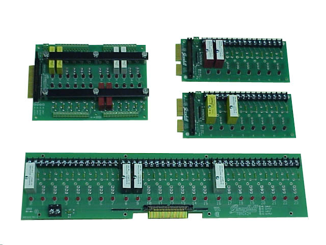
Scientific Solutions Relay Rack Size Comparison
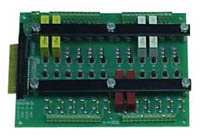
Upper Left: 24 Position Relay Rack for Mini Modules
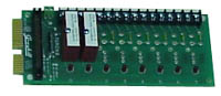
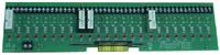
Upper Right: Two 8 Position Relay Racks for Standard Modules
Bottom: 24 Position Relay Rack for Standard Modules
A Solid State Relay Rack is a circuit board that has positions to allow the plugging in of Solid State Relay (SSR) modules. SSR Modules are used to allow a +5v TTL Digital I/O signal to control or monitor AC 110v/220v or DC 60v/200v sources. The Relay Rack has a connector that allows connection of the Relay Rack to Digital I/O signals. The Relay Rack also has screw terminal "pairs" for each of the modules that allow easy connection to your AC voltage or DC voltage signals.
Relay Racks come in different versions to accommodate a different number of Modules. Typical racks accommodate 8, 16 or 24 Modules. Thus, you can select the Relay Rack that can hold the number of SSR Modules that you need.
Keep in mind that many times the Digital I/O from the computer is programmable as INPUT or OUTPUT in 8-bit sections. This means that if you have an 8 position Relay Rack, then it will have either all INPUT or all OUTPUT type of modules. Thus, if you need both INPUT and OUTPUT modules, you would need two 8 position Relay Racks or a rack with more positions such as a 24 position rack.
There are also two types of Relay Racks based upon the size of SSR modules you want to use. One type is used for "Standard" size modules, while the other type is used for "Mini" size modules. Standard and Mini type of SSR Modules are much different in size. A Relay Rack designed for "Standard" size SSR modules cannot use the "Mini" size modules and vice-versa.
Relay Racks have a connector that is used to cable between the Relay Rack and the Digital I/O signals. Typically this connector is a 50 position pin header made up of two rows of 25 pins with one row the Digital I/O signals and the other row ground. If your Digital I/O equipment has a single 50 position header with 8 Digital I/O signals, then using a single 8 position Relay Rack is not a problem. However, if you have 16 or 24 Digital I/O signals on a single 50 position header, then it may be easier to use a Relay Rack with 16 or 24 module positions. If, for example, you want to use two of the 8 position Relay Racks to pick up 16 Digital I/O from a single 50 position Digital I/O header then it gets a little more complicated as to how to wire up from the single Digital I/O header to the two Relay Rack headers.
The Relay Racks and Solid State Modules are normally used with Scientific Solutions BaseBoard / PCI product. On the front of the BaseBoard / PCI are four connections, with each connector providing 24 Digital I/O signals. Each connection can connect to a single Relay Rack. So if you wanted to use two of the 8-position racks, you could use two of the connections on the front of the BaseBoard / PCI. The 24 position rack would connect to one of the BaseBoard / PCI front-panel connectors.
 Technical Specifications
| Picture | Part Number | Description | Module Size | Rack Dimensions |
|---|---|---|---|---|
 |
0381013 | Relay Rack, 8 Module Position | Standard | 8" x 3.5" (203.2mm x 88.9mm) |
 |
0381014 | Relay Rack, 24 Module Position | Standard | 18.75" x 4.5" (476.3mm x 114.3mm) |
 |
0381015 | Relay Rack, 24 Module Position | Mini | 8" x 6" (203.2mm x 152.4mm) |
Specifications subject to change without notice.
Scientific Solutions liability, trademarks, and export notices apply.
Copyright © 1972-2025 Scientific Solutions - All rights reserved.